
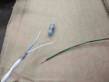
Today I started off my first round of adventures by knocking out the wiring of the P-MAG, starting off with the shielded 2-wire cable that goes to both an ON-ON slide switch (to choose either the “A” or “B” power curve) and a 9-pin D-Sub connector that allows hooking up a serial cable and port to adjust different parameters through the E-MAG Interactive Control and Display, or “EICAD”.
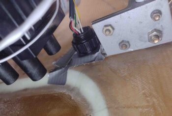
Again, since I originally didn’t have a connector designed on the firewall (well, I did at the VERY beginning but then went away from the idea… now obviously full circle back to it) I just made one long cable. Today I cut that cable and added a solder pigtail to each new cut end… the P-MAG side shown here where I used a Raychem solder sleeve.
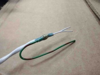
The serial data/power curve ground pigtail is connected to the P-MAG unit’s ground wire, which in turn is grounded to the engine side ground bolt. So I made up this ground wire with a ring terminal for a 5/16″ bolt as well and soldered the two ground wires together.
I also soldered/tinned the ends of all the wires for attaching to the P-MAG terminal block.
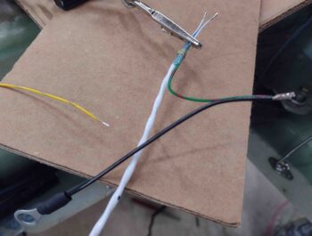
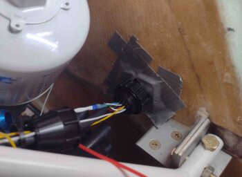
On the freshly cut serial data/power curve cable inside the headrest I soldered in a ground pigtail by hand and simply covered it with heat shrink. Since the firewall (forward) side of the P10 connector has sockets, I stripped the ends of these wires and crimped those on.
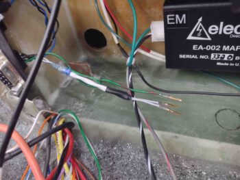
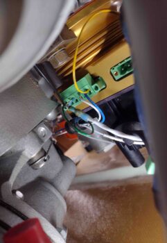
I then spent a good bit of time removing the P-MAG wiring terminal block and populating all the wires into place. When my engine was built I had them install the P-MAG with the wire plugs facing down, which made sense at the time, but the access down there is not great with the mechanical fuel pump in the way of the inboard terminal block/plug anchor screw. I plan on swapping that inboard anchor screw out for a hex head vs slotted since a hex wrench would be infinitely easier to use to get that screw in and out for future maintenance, etc.
I’ll note that I could rotate the P-MAG 90º or even 180º but I still like the wiring down on the bottom. Clearly I don’t plan on wiring up this unit more than once and/or messing with the wiring much once the bird is flying.
I added the yellow wire that sends out the tach signal to the GRT EIS-4000 and also connected up the 18AWG black ground wire. Finally, I routed and connected up the blue (PMAG 12V+ power) and white (P-MAG “P-Lead” Kill Switch) wires that come over from the P9 connector. Add the serial data power curve/EICAD wire pair and that’s 6 connections total for the P-MAG wiring.
Note that I also went ahead and disconnected the other 3 lead coil plug (right side of pic partially obscured) at this time since it needs to be disconnected during the initial P-MAG setup process for safety reasons.
I terminated all the ends of the required P-MAG wires with D-Sub pins and installed them into the P10 connector (except clearly the blue and white wires in P9).
I also crimped pins and terminated the 3 fuel pressure sensor and 1 oil temp sensor wires into the P10 connector as well. This leaves only 4 pairs (8 wires) for CHT and 4 pairs (8 wires) for EGT to install and I’m finished with all the engine/connector wiring except for 3 wires down below: the big yellow starter cable and the alternator’s B & F leads.
Clearly I need to wait until after the firewall covering is in place to connect these wires and the GIB headrest side of all these wires/connectors as well, including the Electroair coil pack wiring.
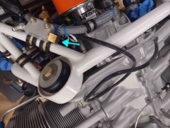
Still on the P-MAG: I connected the included 1/8″ ID MAP sensor hose to the nipple on the face of the P-MAG and routed the hose over to near the MAP manifold block mounted to the top left of the engine mount frame. The setup process of the P-MAG unit requires the infamous 2 puffs of air during the initialization of the unit so I left it disconnected from the MAP manifold until after the setup is completed (note the blue arrow on the MAP manifold where this hose will get connected).
Speaking of the MAP manifold… I’m sorry to report that I received another order from Summit Racing that included a 16″ long -3 AN (3/16″) stainless steel hose with a 90º fitting on one end. The only problem is that I currently have a 16″ hose on hand, thus why I ordered a new one that was supposed to be 12″ long with straight fittings on each end. I have to say this was actually not Summit’s fault since the packaging from Aeroquip had the wrong part number on it.
And as I always say, “better to be lucky than good” since as I was researching the issue on their website I found a 14″ hose which I think will actually work a hair better than the 12″ hose, after some double-checking… to be clear, either a 12″ or 14″ would work, but the 16″ hose is just too long. I’ll call Summit Monday and work out the exchange. Also, since they have to pay return shipping I’ll throw in one of those 120º -6 fuel fittings that is just not angled well.
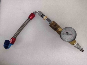
I then switched gears and assembled all my collected bits and pieces from yesterday to test out my 3 each -4 hoses. From my old painting days (chopper motorcycle project pre-Long-EZ) I grabbed a pressure gage setup and added that to the mix. I then attached a -4 nipple to an air hose quick disconnect fitting and Voila! Pressure test kit ready to go.
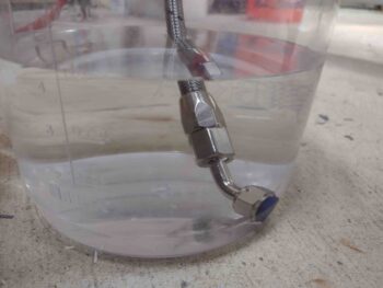
I then tested the oil pressure sensor hose. I noted on the 150º hose end that the -4 sealing cap needs a little extra oomph to keep any bubbles from forming in the little side hole. But beyond that it passed the test perfectly.
With the oil pressure and fuel pressure (sorry, no pic on that one) sensor hoses good on the pressure tests, I then pressure tested the fuel injection servo to fuel distro spider -4 hose.
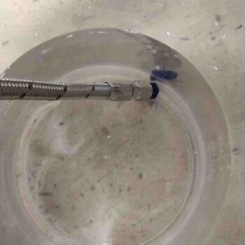
Again, all was good with this -4 fuel outlet hose pressure check.
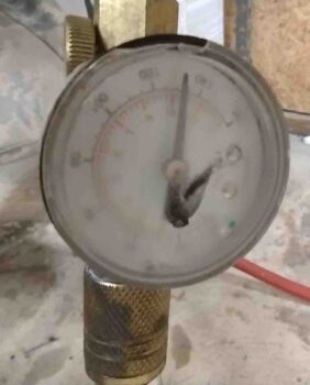
I grabbed a shot here to show you that I pressure checked all these hoses to a hair over 130 psi. The Silver Hawk manual says to have the fuel lines good to something like 1000 psi, but, um, sorry Precision Airmotive guys but my shop compressor ain’t got that in it! This will have to do.
Tomorrow I’ll test all the other hoses I’ve made so far. I’ll probably start my -6 fuel hose from the mechanical fuel pump to the FI servo inlet but won’t be able to finish that hose until next Wednesday when I receive my next round of 120º hose end fittings… yes, I’m going to be OCD on this one guys.
Finally, I should be wrapping up all the nit-noy prerequisite (self-determined) tasks on the engine to the point where it will come off the bird soon so I can work the oil lines and reinstall/re-clock the engine oil inlet fitting (it’s pointing up vs down). I’ll add some Adel clamps to the front of the accessory case as well. I’ll finish by noting that I need to do some AD stuff on the P-MAG and will talk to Brad at E-MAG Air. I might even send the unit back for any final and latest updates if need be before I go live with it operationally. More to follow on that.