
I started off today by finally getting in touch with Clinton at Custom Aircraft Parts to have that much needed, serious discussion about the exhaust pipes. Clearly there are some inherent limitations in what Clinton and his team can do being in California and my being in North Carolina. As Clinton noted, they could make me a set of custom exhaust pipes if they had access to the bird to determine the requirements first hand. Thus, unless I go with a local vendor, which I might just do, cutting and re-welding is out in regards to Clinton & Co. doing it.
Another option is simply to return the pipes for a refund. Of course this gets me nothing since these are a must have item. The lower cowling will get reworked before these things go back since, again, you can’t run an engine without exhaust pipes. Moreover, from what I’ve observed with these pipes and other aircraft components, most cost 1.5-2 times of what I paid for them… no thank you to that!
The last option, which is dichotomy of scary as hell and probably/likely the most potential to effect real results is to do some surgery on these pipes myself, as detailed to me by Clinton over the phone. Since these exhaust pipes are actually 2 pieces held together by a couple of springs, the best area to minimize height for these pipes is where the outer pipe slips over the inner mounting bracket sleeve, with the latter being welded to the mounting flange.
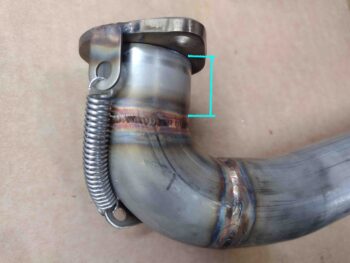
The total height of this possible area of reduction is 1.2″. Talking with Clinton, he recommended leaving at least 3/4″, with a max removal of 1/2″. Now, as with any surgery there are requirements, parameters and risks.
- Whatever amount comes off the outer, female pipe collar must come off from the inside sleeve as well.
- The removed material must be parallel to the original edge on both pieces, with the edges straight and clean to maintain an optimized seal to prevent exhaust leaks.
- With significant shortening of this collar, new, shorter springs will be required.
But, as I’ve noted countless times over the last couple of months: compromises are unavoidable and I’ll take what I can get. I’ll prognosticate that this will be another PITA process to be sure, but on the other end any significant cowling clearance will be worth it. I’ll assess this process further and also next steps [local cutting/re-welding and/or re-working bottom cowl] if/when this initial task is complete.
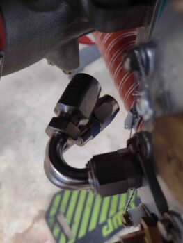
After my phone call with Clinton, and my note-taking and mental processing of what all is entailed with the exhaust pipe surgery, I then called Summit Racing. I told them my tale of woe involving the 2 different 120º hose end fittings and asked if I could do a partial order and still get free shipping. They agreed, so it was worth another $40 at a shot of getting a CORRECT angled hose end fitting for my Fuel Injection Servo inlet hose… or at least a better-angled fitting than either of the two I have now. I will note that the amount I’d spend in shipping to return either one or both of the two offending hose ends I have on hand now would be spending a third to half of what they originally cost (with free shipping no less). So they’ll go into bench stock for now and maybe on Ebay someday.
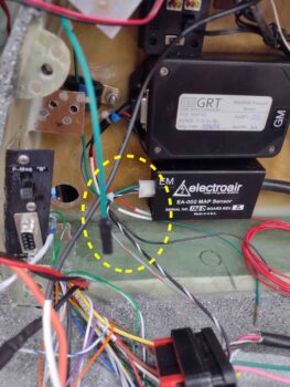
On to more benign build tasks: I received the Electroair MAP sensor Molex connector with the requisite sockets. After a bit of digging into the manual to confirm I wasn’t screwing anything up, I then terminated the sockets onto the appropriate wires, got them into the appropriate positions and finished off the wiring to the electronic ignition MAP sensor.
Before I decided on using CPC connectors to transition the wires through the firewall, I had labeled and terminated a white 22 AWG wire into the GRT EIS D-Sub connector for the Oil Temperature sensor. With the new connectors in play I simply cut this wire in half, which gave me a nice labeled segment. I then terminated a FastOn connector onto the end of this freshly cut wire and plugged it onto the Oil Temp nub on the front of the engine accessory case.
Voila! Oil Temp wire installed and ready to be terminated into the right side engine-firewall connector: P10 (see below).
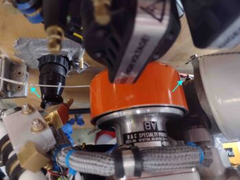
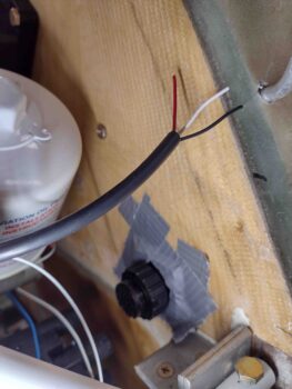
As I did on the left side, I then duct taped the firewall side of the P10 connector plug to the firewall in its respective hole. In this pic below, from left to right you can see the engine-side P10 plug strain relief zip tied onto the freshly cut fuel pressure sensor cable (note the internal wires). The OT sensor wire is also through the strain relief while behind it are the blue and white P-Mag wires from the P9 connector.
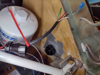
The fuel pressure sensor inputs only require the red, white and black wires, so I cut off the green and bare wires from the cable. This pic also provides another shot of the firewall P10 connector plug.
Today was one of those days of a lot of corroborating, research, coordinating and prep without a lot of work actually getting done. I did get all the components assembled and prepped to pressure test my oil and fuel hoses, so tomorrow I hope to get a lot more actual work knocked out.