
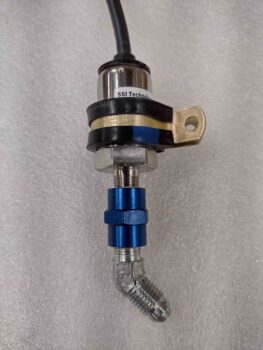
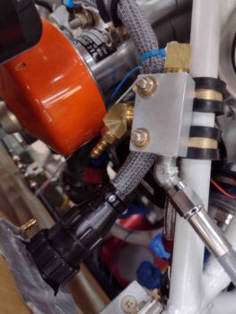
I started off today by gooping up the threads and torquing the AN fittings onto the GRT fuel pressure sensor.
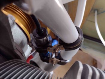
If someone would have told me that this next task was going to take 3 hours, I would have told them they were cuckoo for cocoa puffs… and I’d have been wrong. Adel clamps are a big enough PITA to install without chewing them to pieces, but due to about zero working space and being blocked from getting tools in place either from the engine mount itself or a big cylinder on one side to the P-Mag on the other… it was simply a rough time installing these 4 Adel clamps at angles to secure this sensor in place. But perseverance, a lot of expletives and countless dropped tools and/or hardware (perhaps even a couple propelled tools . . .) won out.
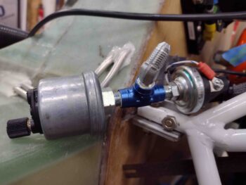
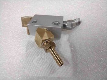
Here we have the diminutive but huge PITA to install GRT fuel pressure sensor.
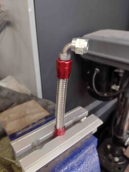
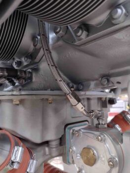
Jumping ahead a bit, I repurposed my previous top hose end fitting and blue fire sleeve from my fuel injection servo to fuel spider -4 hose and added a new 90º hose end on the fuel pump side. With the straight hose end side fire sleeve already secured in place, I used my Clamptite tool to wire clamp the fresh cut side in place as well. To be clear, I just cut off about the last 4″ of the previous hose and fire sleeve and simply added a new hose end on the other end to make up this new hose.
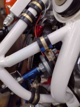
By swapping out the straight nipple on the bottom end of the FP sensor with a 45º fitting, it again allowed me to re-use the straight hose end fitting from the fuel spider. Although the space is tight in this area, the hose went on without an issue.
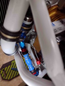
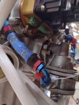
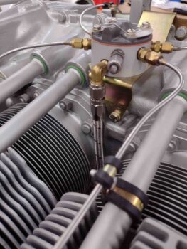
Speaking of 45º AN fittings… after assessing the hose attach configuration for the oil pressure sensor block, I removed it from its temp Adel clamp attachments to goop up and torque the 45º fitting into place in the center position of the aluminum NPT Tee fitting. I’ll note that this fitting required clocking at a forward facing (pointing down) inboard angle to get the most optimized fit for the interfacing 150º hose end.
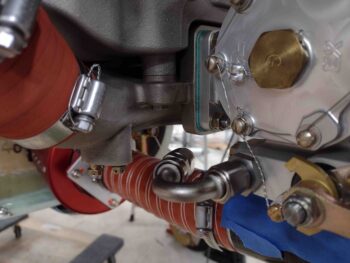
With the hose length and required hose end fitting clocking requirements in hand after my recon, I cut and installed a 150º hose end on the opposite end of the one shown at the top here.
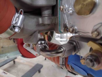
The 150º hose end at the other (bottom) end of the fuel pressure sensor hose worked out nicely with the Tee block’s middle 45º fitting facing downward and clocked inboard just a bit.
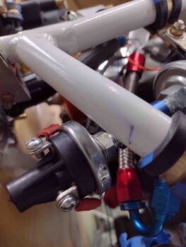
A little extra length to a hose provides a tad more flexibility (read: less stress & tension) and ease during install, so that’s what this combo offers. It actually worked quite the treat even in such a tight spot.
I’ll further note that I swapped out the temporary standard nuts on the Adel clamps and did a final install on those with MS21042-3 nuts.
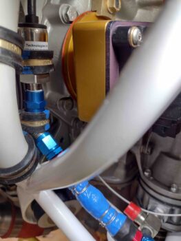
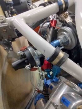
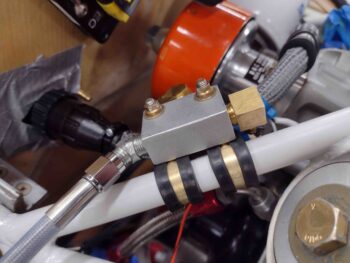
With no kidding final installs on both the fuel pressure sensor and the oil pressure sensor block, it was now time to go final on the MAP manifold block. I gooped up the 1/8″ NPT threads on the newly acquired 3/16″ barb fitting and torqued it into place.
I then did a final install on the MAP manifold onto the engine mount, again swapping out the temp nuts for MS21042-3 aircraft grade nuts. Although I just ordered the correct 12″ length -3 AN hose for connecting the MAP manifold to cylinder #3, I attached one end of the current hose to show how the connection will work.
This completes all the external sensors and sensor components that I’ll be installing onto the engine mount. The only sensor-related items left to install are the CHT and EGT probes that mount to the cylinders and exhaust pipes, respectively.
It was late and I was about ready to call it a night, but I had everything sitting in front of me to knock out the new -4 fuel line from the fuel spider to the Fuel Injection Servo outlet port… so I did.
Here we have the new, more demurely colored hose end fitting attached to the fuel distro spider.
Down below I used a 45º fitting to attach this -4 hose to the FI Servo. I’ll note that I will in fact fire sleeve this hose (upgrading to orange vs blue) and that the hose itself is cut from the longer hose that originally came down from the spider.
My last task of the evening resulted in a bit of head scratching. I quite often buy extra fittings so that I have them on hand when need be and I don’t end up paying extra for shipping, as I did today on a small order I submitted to Summit Racing for the shorter stainless steel “vacuum” hose that will connect the MAP manifold to cylinder #3.
That all being said, I ordered 2 each 120º -6 hose ends to use one of them to connect the main fuel line to the inlet fitting on the LEFT side of the Fuel Injection Servo. Well, here they are… both right out of their packaging… different well known brands mind you, but clearly one thing is not like the other angle-wise.
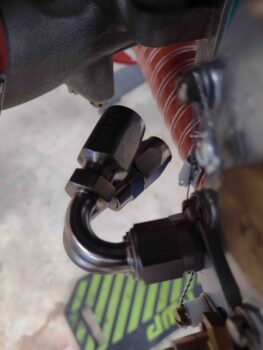
Does it matter? How different are they? Let’s take a look. The first one curves around decidedly inboard to the right, about 3-5º seriously more than I’d prefer. The other one very noticeably points outboard to the left, and with a fire-sleeved stainless steel hose installed will be just barely —if at all— able to clear the cold air plenum’s cable-mounting extrusion.
And all I wanted was one that splits the difference and shoots “straight” towards the forward right engine mount. Yes, I know: first world problems.
Tomorrow I plan on doing some engine-related wiring and pressure testing all the -4 hoses I made up today. The jury is out on whether I’ll press forward with either of these -6 120º hose ends or if I’ll call Summit and maybe order 1-2 more, if they’ll ship for free. Regardless, I’ll press forward with more engine stuff… I suspect within the next 2-3 days I’ll pull the engine to work the oil hoses, etc. on the front face (accessory case) of the engine. Many tasks to complete with the engine off the bird.