
I started off today by pulling the peel ply and trimming the sides of both outboard 2-ply CF layups for the top cowl cross rib baffle/stiffener. I then mounted the top cowling back on the bird to check for any possible clearance or obstruction issues, but all was good (no pics). I of course meant to do the next round of layups on the cross rib baffle later in the evening to let it cure overnight… but ran out of time.
Before I mounted the bottom cowling to work on the armpit inlet inboard walls, I wanted to get another smallish task knocked out: the engine ground strap attachment. I discussed different engine ground strap attach points with B&C Electronics and was “cleared hot” by them to mount it to the front right corner edge of the oil sump. The only issue is that when I ordered this ground strap from them years ago, each end was meant to attach to a 5/16″ bolt. Now this end is attaching to a 1/4″ bolt.
In the recent past I had looked around for a small insert to use but didn’t have any, and honestly couldn’t find any anywhere online. I ended up ordering some raw stock from McMaster-Carr and since I don’t have my Lathe CNC finalized yet, decided to simply trim a width off of it that is as thick as the ring terminal: ~1/16″. I then spent less than 10 minutes filing the insert to final thickness and to remove the Dremel cut marks.
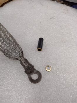
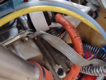
I then removed the front right bolt from the oil sump lip. Now, I had originally planned to mount the grounding strap on the top of the oil sump lip, but it was too close to the engine mount ring when pointed in the direction it needed to be to reach the firewall post, and stretched too tight if I kicked it out in different position… so I mounted it on the bottom of the oil sump lip. I then added some blue Loctite to the bolt threads, applied some Dielectric grease to the ring terminal, replaced the star washer and then torqued the nut back to 96 in-lbs. I then did a continuity check from the far unattached end of the ground strap to the bolt stud on the starter and it rang out nice and loud.
Voila! Engine ground strap installed on the engine side.
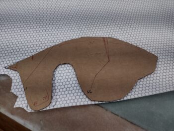
I then mounted the bottom cowling and spent a good half hour finalizing the shape of the left side armpit inlet inboard wall. I then used the cardboard template to cut out a ply of Lantor Soric filler material, with some minor mods (I didn’t want to have to remake a whole new template).
I then used the Lantor Soric to cut out a ply of CF for the left side (I explain below how these are used).
I then spent nearly 45 minutes working the right side template for the armpit intake inboard wall. I don’t show Mike Melvill’s original template here, but just like the left side template mine is significantly different than his.
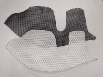
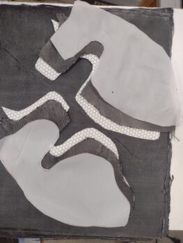
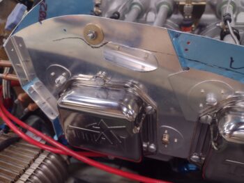
I then did the same thing with the right template by using it to cut a ply of Lantor Soric, and then using the Lantor Soric to cut a ply of CF. I then cut peel ply for both side layups (pic 1).
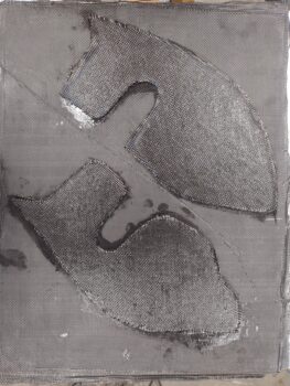
Now, included with the Mike Melvill cowlings from Feather Light was a large flat piece of 3-ply (I’m assuming?) CF. It’s a bit too thin and flexible (emphasis on thin) for how I want to employ it, which is a bit more outboard than Mike had his (it appears my ramps are a tad narrower than how Mike Melvill’s ended up… which is fine). I kept going back and forth but eventually decided I wanted these inboard walls just a bit thicker, thus the Lantor Soric getting added to the 3-ply CF sheet with another ply of CF over the Lantor Soric… as you can see that’s exactly how I laid it up (pic 2).
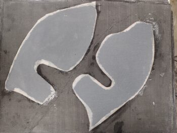
I then of course peel plied both layups and since I used Pro-Set epoxy I set them aside to cure overnight.
I was heading out for a later dinner with Jess so I decided to simply knock out a couple more baffle tasks since I wouldn’t have enough time to make a new top cowl cross rib middle template/form and then do a layup.
Again, I have a couple rivet holes remaining on the left side front baffle that are not in an area that will simply allow me to cover them with baffle seam material. As I did on the right I trimmed the length of the front side stiffener way down and then cleaned it up, final drilled the #30 holes and mounted the stiffener with 2 rivets.
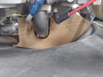
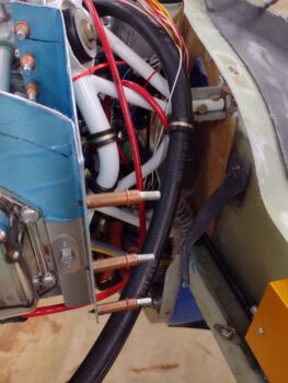
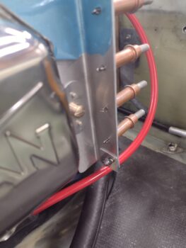
My next baffle task entailed a bit more machinations. First off, while the bottom cowling was off I took a good look to assess the run of the crankcase vent hose. In the vicinity of the lower right front baffle/cylinder 4 corner is where a 5/8″ aluminum tube will get secured inside the hose to then run along the exhaust pipes so anything coming out of the hose/tube will get burned off at the exhaust exit.
You can see in the pic below that the crankcase vent hose is secured upstream to the engine mount frame with an Adel clamp, and I need another one at the bottom front corner of the baffling to again secure the hose.
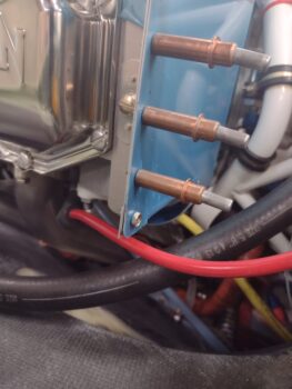
Whether the Adel clamp gets secured directly to the bottom corner or maybe with an intermediate angled tab, I need to be able to bolt either to the bottom corner of the baffle. I drilled out the bottom rivet hole to 3/16″ and then grabbed a scrap square of 0.040″ thick 2024 aluminum as a reinforcement doubler and cleaned it up. I then mounted an AN3 platenute just to the side cylinder 4 baffle segment with countersunk rivets.
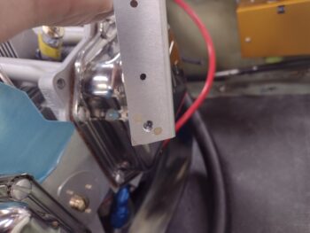
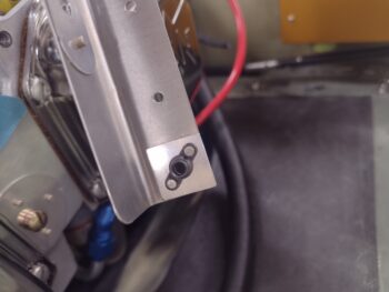
I then reassembled the front right corner baffle segments and threaded in an AN3 sized bolt. Again, I may need to make up a small tab to secure and angle the Adel clamp in the correct orientation, but the hardpoint for attaching all that is now in place.
I was expecting to receive the cylinder baffle forms by today, but I haven’t gotten them yet. If I don’t receive them by Tuesday I’ll ping my contact to see what’s going on. I plan on finishing up the top cowl cross rib baffle over the next couple of days and add some reinforcement brackets to the “Melvill” baffle bracket on the aft right side. After that, I may add some baffle seal material around the front and side baffles a bit, but I can’t really do any more on the baffles and will roll into working the exhaust pipes and prepping for micro finishing the remaining parts of the bird.