
I’m kicking off the nose and canopy build with another 3-DAY BLITZ which we’ll call Round Two. Essentially over the next 3 days I’m going to clean up some low hanging fruit tasks from the engine and also prep the internals of the nose and avionics bay (forward of the instrument panel) as a prerequisite for putting a lid on the nose. For those of you who follow my blog I’m sure clearly by now you realize I don’t like minimizing access to a given area that I will then later have to go back and do a fair amount of work in. The stuff that goes in the airplane either has to have time spent on it going in now or later, and if I have access now it might as well get installed while it’s significantly easier to do so. So I am!
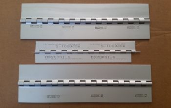
I started off the day by receiving a delivered order I placed while in NC for a set of new MS20001-12 hinges for the canopy. After the issues reported by both Dave Berenholtz and Mike Beasley on the smaller MS20001-6 hinges called for by the plans, I figured I would make the decision early to implement these and save myself some pain. So while down in NC I spent some time scrounging around online to find a source of supply for just a couple feet of these quite expensive hinges.
I then got to work finalizing a comprehensive order I’ve been building at Aircraft Spruce for well over a week. Included in this order is one of the last of the big ticket instruments I’ll need for this build: the Trig TT22 Mode-S Transponder. However, before pulling the trigger on the order I needed to determine my CAMLOC/Skybolt requirements for the wheel spats, which I did by measuring the thickness of the wheel pants and bonnet at the mounting hole points. I then ordered a representative number of those CAMLOC/Skybolt components to test out. Once the correct sized studs, receptacles and associated hardware are confirmed/dialed in, I’ll order the remaining components.
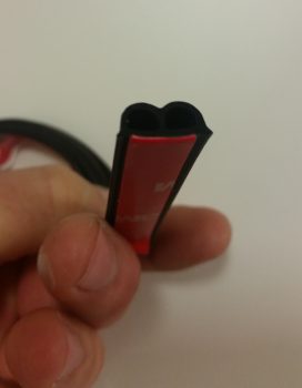
Then, per my discussion with Nick Ugolini about a year ago, I also determined that to get 30% compression (actually 37.5%) on my 0.2″ thick canopy “B” seal I need to compress just over an 1/16″ of an inch and have a 1/8″ spacer to keep it from going more than that. Again, as per discussions with Dave Berenholtz and Mike Beasley, I’ll build this gap into the left canopy frame side rail that rests upon the longeron so that it’s in place prior to glassing the canopy frame. The final practical result will be a 1/16″ plate affixed to the left longeron both at the forward end and the aft end, with a matching set affixed to the bottom of the left canopy rail to create the 1/8″ gap for the proper compression of the “B” seal [BTW, I think I finally found that “pleasing shape” that Burt is always telling us to strive for in the plans! . . . haha!]
Moving on…
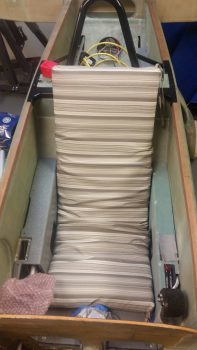
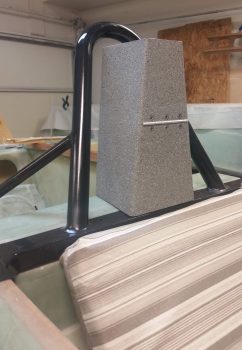
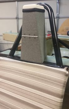
As I was running around doing some errands today, I picked up a cheap 17″ x 43″ x 2″ thick outdoor chair pad to use in the final dialing-in of my rudder/brake pedals, my canopy height and panel/F28 height (for visibility). The pad fits so well I think I’ll use it as a rough template for my seat pad when I get to that point (Chapter 26 – Upholstery).
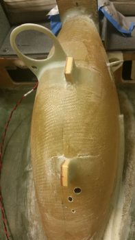
I then started in on the process of adding a thin ply of insulation to the nose wheel cover (NB). As I assessed adding insulation to NB, I decided I didn’t want to run the wires for both the 12V cigarette lighter charger (left aft side of NB) and the USB charger (right aft side of NB) in a circuitous manner. Instead, I wanted them to go as straight from Point A to Point B as possible, which means running the separate set of wires under the lower edge of the NB insulating material at/in the intersecting corner of NB to the fuselage floor.
Since the cigarette lighter adapter also serves as my PC680 battery charging port, and is subsequently connected to the Battery Buss, I used 16 AWG to ensure a robust connection. I terminated the charging port end with the PIDG Fast-ON terminals included with the charger, twisted the wires together to mitigate any electromagnetic noise, and then labeled the wire pair.
I then did pretty much the same thing on the USB charger side (right) only with 18 AWG wire. I still have to mount the USB charger in the corner between the aft side of NB and the lower instrument panel, which I’ll knock out during this 3-DAY BLITZ.
I then whipped a small batch of epoxy with fast hardener and made up some wet flox. After I filed down the round countersunk heads of the Electroair screws into a triangular shape to give flat gripping edges, I then floxed them in from the aft side of the firewall into the D-Deck area for mounting the Electroair MAP sensor unit.
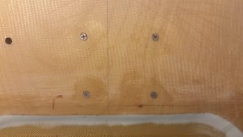
Here are the 4 stainless steel countersunk screws from the firewall side.
And here’s an even closer shot of the 4 stainless steel countersunk screws that will secure the Electroair MAP sensor in place. As you can see I peel plied them to ensure the firewall surface remains even and smooth.
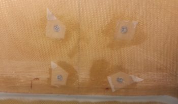
A few hours later after the flox had cured I pulled the peel ply from over each screw.
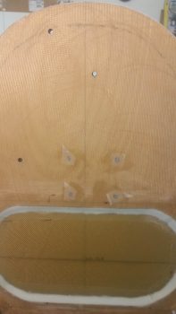
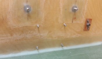
 Here we have the 4 Electroair MAP sensor mounting screws floxed in place from the aft firewall side.
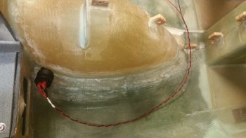
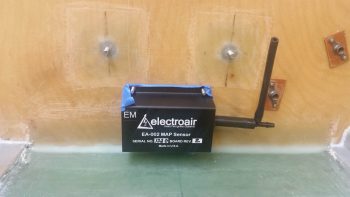
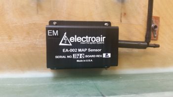
And the Electroair MAP Sensor set in place on its 4 mounting screws.
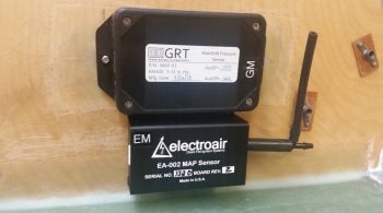
And here are the two MAP sensors that will be in use on this airplane: the top-mounted GRT MAP sensor and bottom-mounted Electroair Electronic Ignition MAP sensor. As a point of note, the MAP line does actually run to the PMag in the engine compartment as well.
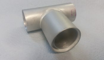
With the epoxy I mixed up to flox in the 4 Electroair MAP sensor mounting screws, I also whipped up some micro paste to secure a length of 1.75″ x 0.035″ wall 6061 tubing over the existing 1-1/4″ tube that exits off the left side oil heat air duct that heads towards my left foot. This all will be located just forward of the lower left instrument panel and I needed this thicker diameter attach point for 1-3/4″ SCAT tubing that will feed the panel-mounted eyeball vent for heating a critical component of the aircraft: the pilot!
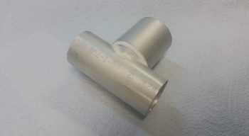
Here’s the top side of the tube addition to allow 1-3/4″ SCAT tubing to be attached to feed the panel mounted eyeball vent.
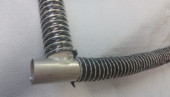
Here’s a mockup with the SCAT tubing to show what I’m talking about. The 1-3/4″ scat tubing is vertical while the 1-1/4″ scat tubing (that heads to the left foot vent) is horizontal.
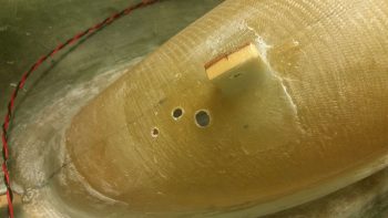
I then measured, assessed, determined and drilled the 3 holes required for the 3 separate OAT probes I have for the panel: 1 each for the HXr EFIS, 1 each for the Mini-X EFIS, and 1 each for the MGL Clock/OAT. I emulated Marco in his placement of his OAT probes since on the forward side of NB the OAT probes remain internally clear of the nose wheel when it’s retracted. I wanted the OAT probe mounting holes situated because I’ll use this location to provide a glass-to-glass bond to secure the NB insulation in place.
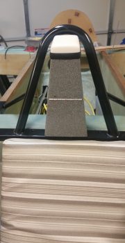
Today was the first day in a LONG time that has been warm enough for painting. Since my pilot headrest was still taped up from the first round of painting this was definitely low hanging fruit. [You may remember the cans of spray paint, although labeled the same, were distinctly different colors so I dumped my 2-tone cabin paint scheme and am simply going with one color]. I painted a couple of coats of the gray granite on the head rest and then after about 4 hours I hit it with a couple of coats of matte clear coat. A few hours later, when the clear coat had cured to the point to allow handling, I removed all the protective tape from the headrest.
I then attached the RAM air ball with a screw and put the keys back in the lock (mainly in an attempt to help keep track of all this stuff!).
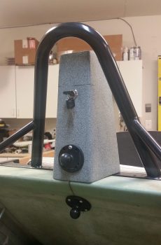
I then set the GPS antenna “radome” back on top… just something for a little fun and to spark some conversation at fly-ins! (grin)
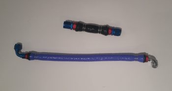
I wanted to also knock out the last couple of engine hoses that were available for fire sleeving… Again I sealed the bare fire sleeve ends with 3M fire barrier and then covered those sealed ends with narrow strips of black heat shrink. Top black hose is the oil heat oil return line back into the sump while the bottom blue hose is the fuel pump to fuel injection servo feed line.
Tomorrow is roughly day 2 of my 3 DAY BLITZ on the nose components and I intend to be doing a fair amount of glasswork.