
Today I machined the final throttle cable tab to finally get this part installed.
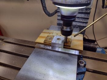
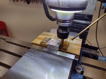
I cut off a 1.5″ wide piece of 2024 angle and mounted it in the milling machine’s vise.
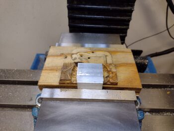
I then milled each side to create a new throttle cable mounting tab.
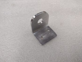
Here is the initially cleaned up final throttle cable mounting tab . . .
Which I then mounted the throttle cable into before mounting the tab to the throttle cable bracket.
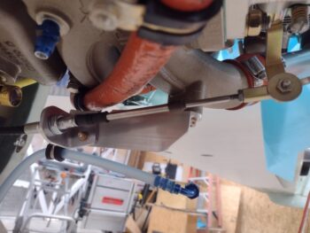
With the throttle cable mounting tab position and configuration finally complete, I then got to work finalizing the throttle and mixture cables’ installation in both the front and back seat areas.
I have to say that it took a good few hours to actually get these cables installed. Of course this area of the plane is one of the most difficult to work in, and, additionally, I also did a final install on the oil heat system’s 3 cables… which besides routing included swapping out temp hardware for final A/C grade hardware.
I installed the pilot throttle quadrant to test out my new throttle handle cable configuration with it secured in the Adel clamp. The cable movement/clearance looked promising, but my cable clearance evaluation was cut short by the fact that my newly modified cable cover was too long… it was now the culprit in causing clearance issues.
I went back in the house and reverted back to a shorter version of the cable cover and kicked off yet another 3D print. Thankfully it took less than 20 minutes to print this thing out.
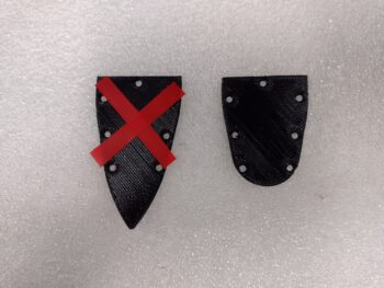
I then mounted the shorter version of the cable cover on the throttle handle/lever for another round of throttle handle cable clearance checks. Note the black abrasive-resistant heat shrink I put on the throttle handle electrical cable.
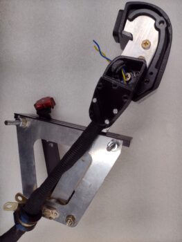
I then reinstalled the throttle quadrant and checked the cable clearance with it pinned to the sidewall in an Adel clamp. While the clearance is pretty darn good, I’m sorry to report that it’s not 100%. I will need to trim a bit of the top mounting throttle quadrant mounting nubs on the sidewall a bit. The good news is the amount I need to remove off of each nub is significantly way less than what I was planning on before.
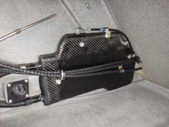
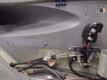
A few more things to point out in the pic below: The throttle and mixture cables are final mounted into the sidewall cable bracket. Also, it may be hard to see, but I have a thick piece of protective rubber wrapped and zip-tied around the throttle and mixture cable pair coming through the pilot back seat bulkhead. Finally, note the electrical switch box at the top center of the pic . . .
This is another sideline CAD/3D print project I’ve been working on the last few days as well… doing a print here and there either before or after my other larger 3D prints. It’s a rather diminutive 2x mini-switch box for the GIB lights enable/disable circuit and a spare switch. Here’s a closer look.
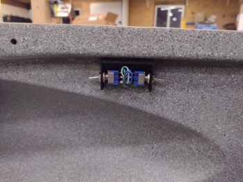
After trimming the 2 pairs of wires exiting the sidewall just under the longeron, I soldered the wires to the 2 mini switches. I then installed the switches in the box exiting each end, and applied velcro on the box and the sidewall/longeron to secure it in place.
I had also 3D printed a cover for the box that didn’t look so hot, so I cleaned it up and hit it with a few coats of primer and then black paint. I’ll show that here within another day or two when I install it as well.
My goal as I work the throttle & mixture cables and associated quadrants is to clean up and finalize the install of the left cockpit wall components, from the instrument panel aft. Yes, it will add a few days to the throttle and mixture cable installs, but nearly everything will be done cable, duct and electrical -wise on the left sidewall… leaving pretty much only the panel forward requiring wiring and component installs. That being said, tomorrow I plan to do the no kidding throttle and mixture cable configurations to dial those in once and for all.