
Overall, today was another one of those figuring it out days with not a lot of actual building, but I would say definitely a fair bit of progress. Still a lot more CAD work and prototyping. How much of it is required? Probably less than I think, to be honest.
As I 3D print some objects I start baselining other parts that may need streamlining. Having worked project management for years, I often go back to what my requirements are… the problem being sometimes I don’t remember them precisely in the mad rush of things.
At one point I wanted an in-line butterfly valve in the air duct to the panel mounted eyeball vent. Over the past few days I started down the road of making a 90º elbow with internal butterfly valve for the vent, with only a nascent effort of mic’ing up the part and printing off a few sub-10 minute rings for the initial interface. This all being done with a few minutes of setup and then Bob whirring away as I do other stuff.
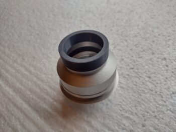
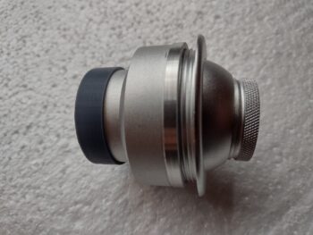
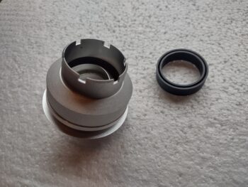
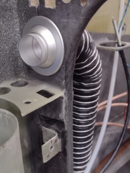
The initial fitting came out well, before remembering that I was going to start out with just the eyeball vent closing mechanism —sans butterfly valve— to shut off any unwanted air. At over $100 for the vent I would hope that it could handle this task! Thankfully I had only about 20 minutes into this prototyping before I saw the light . . . and reiterated to myself the true primary requirement: get this bird in the air!
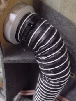
In short, just hook up the damn SCAT tube to the vent . . . done!
So yes, K.I.S.S . . . . is the emphasis on Simple or Stupid?? Or both?
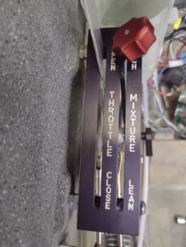
I then repeated almost the same scenario in dealing with my throttle handle wire cable… although this has involved years of pondering and head scratching. The main issue is getting the cable routed down between the sidewall and the quadrant. Closely associated with that is protecting the cable so that it doesn’t get tore up or snag while the throttle handle/lever is moved forward and aft countless times over the coming years.
In focusing on protecting the cable with a hard-mounted, pivoting channel, I was running into the issue of the angled quadrant mounting nubs on the sidewall (I would use arrows here but apparently GoDaddy has forbade such tomfoolery!). They were preventing any of my reasonably designed pivot action from reaching the range of motion required without jamming the throttle before reaching the fore or aft stops.
I had removed the new throttle lever and mounted handle, put the aluminum blank lever back in and was literally mere seconds from marking and cutting the inside edges of those mounting nubs when the thought of an Aeroquip info sheet on how to route hoses, which I had just unearthed half an hour earlier near the shop computer and gave a quick once-over, popped into my head. It said not to run hoses straight from point A to point B, but to add in a curve for stress relief.
Ok, what if I employed that here? I had always tried to run the cable pretty much straight up to the throttle handle, as it dragged the cable fore and aft strapped into the same motion as the throttle lever. What if I disassociated the movement of the cable with that of the lever, to the best degree possible? In other words, make the pivot point of the cable much higher than just matching it to the lever’s movements.
I tried pinning the cable to the sidewall with an Adel clamp smack dab in the middle, but it was a very tight fit with the levers and cable rod ends so close… of course I don’t want any jam-ups on this system.
Experimenting with it a bit more I realized that if I took the cable down the center of the quadrant with a 90º curve to horizontal that it did virtually the same thing as mounting the cable straight in the center. It pinned the cable vertically near the center of the quadrant and it angled/pivoted itself much less than the throttle handle/lever, but didn’t limit any travel.
Bingo! Voila! Years of trying to figure this out and I found the answer serendipitously literally seconds before implementing a much less elegant (or simple) solution! Sorry, I was so stoked that I failed to get a pic and jumped right into mounting a Clickbond for the Adel clamp. I’m going 90º to the aft side since that gives me the best clearance for the cable, which is plenty long enough to make it to the P4 bulkhead connector forward of the panel.
On the other end of the plane, after one more final tweak I hit paydirt on my throttle cable tab that mounts the actual throttle cable to the engine throttle bracket.
Before I had been hyper focused on the clearance between the throttle cable and the fuel hose… just enough to ensure no contact even with engine vibrations.
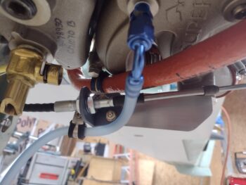
Here’s another shot of the 3D printed mockup to lock down the angle and position of the throttle cable mounting tab onto the throttle cable bracket.
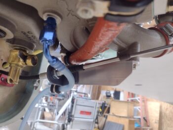
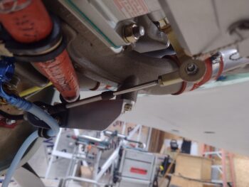
However, I noted with the previous position of the throttle cable tab it was just beyond the limit of the 7º up pivot range of the throttle cable rod. It was barely noticeable when the servo throttle lever was near center travel, since that is its lowest point. But moving this lever through its full range it became obvious that if I pushed it, it was going to tweak something in a bad way.
To be clear, it wasn’t like that originally, but minor movements can translate into being significant… clearly my clamped tab moved enough to cause the issue, even when I thought I was confirming good travel. All is good now though and tomorrow I plan to machine another throttle cable mounting tab.
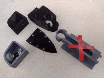
By the end of the day I had collected quite the bounty of 3D printed parts. Note I switched to the black PETG plastic as these are the final versions… or at least I intend them to be the final versions, barring any unintended consequences dictating otherwise.
Starting in the top right (pic below), this is the final version of what I have in the lower left of the pic… I noted when testing out the position of the throttle handle that my pinky rested right on the top front corner of the throttle electrical cable routing block (middle top). Since I had a spare PTT momentary push button switch I went ahead and made a recessed mount for it. I also designed a conduit from the bottom of this button housing through the throttle electrical cable routing block for the pair of wires to run along with the main throttle handle wire cable.
The iron looking thing in the middle is the cover plate that secures the cable into the routing block, and originally secured the pivoting cable guide on the right side (red X’d)… but I no longer will be using that since the cable will be pinned to the lower sidewall via an Adel clamp. I did extend the bottom (pointed) end downwards over 1/2″ to help guide the cable and keep it off the sidewall.
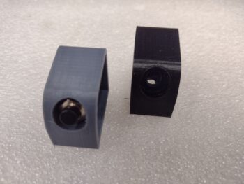
Here is another shot of the top PTT switch housing in gray (prototype) and black (final version).
Tomorrow I plan on getting these new, final components installed onto the throttle handle/lever and also get a new throttle cable tab machined to finalize the engine-side throttle cable installation.