
I jokingly refer to my 3D printer as “Bob” with my friends and family, and Bob has been quite busy today in his quest to help me build this plane. I’m still working prototypes and versions of the throttle cable routing guide and other 3D printing projects for this bird as well. I’ve been rolling from one 3D print to the next and spent a fair amount of time on CAD today tweaking all the modeled parts.
Here’s the latest version of the actual throttle cable guide pivot piece… I added wings to it which will be much easier to explain why when I mount it and grab some pics.
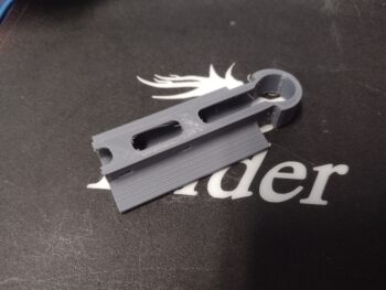
One part that I had to go back to was the throttle cable tab that attaches the cable to the throttle cable bracket. I tested the geometry —which looked spot on— but something definitely got lost in translation and I’m now tweaking the tab placement to mount it in place. I’ll grab pics when it’s installed for good. I’ll note that I had planned on doing the final, no-kidding setting of the throttle and mixture cables and levers to their final positions from A-Z, but this bracket tab being off gummed that up until I get the geometry set right.
I then checked the height and configuration of my throttle handle mounted on its newly machined throttle lever. To do this I mounted the left side armrest, put the front seat cores in, and even mounted the cupholder in place.
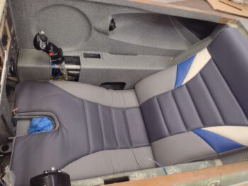
I then climbed in and made airplane noises for a good 30 minutes checking the fit and assessing the operation of the throttle handle and quadrant.
I have to say that I think I nailed the height of the throttle handle! I was fully expecting to have to make another throttle handle lever but this one is spot on… I’m keeping this lever installed and pressing forward.
Here’s a shot specifically of my leg pressed up against the left armrest and the throttle handle. You can see that if I brought the throttle handle down any lower that it would start digging into my thigh, especially at higher throttle settings.
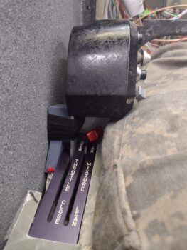
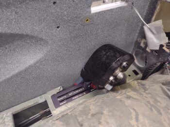
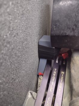
Here’s a shot of the throttle handle wire cable guide on the outboard side of the throttle handle. When I made my video the bottom bolts of the throttle quadrant were not seated in all the way, which resulted in the top of the throttle handle leaning outboard… which in turn resulted in the cable guide being pushed up much tighter to the sidewall than it actually is, as you can see here. Yes, it’s tight, but there is notable clearance. I knew something was a bit awry but pressed forward to get the video finished and uploaded.
I’ll of course work this cable routing issue until it’s acceptably configured. I’ll add that in addition to looking at this cable routing, I also did a bit of assessing on the micro-switches that will need to get mounted to the underside throttle quadrant frame to ensure no clearance or configuration issues rear their ugly heads betwixt the throttle cable routing and the micro-switches. At this time I have 3 functions that require 2 micro-switches: one DPST on the front side (full throttle) and one SPST on the aft side (throttle <10%).
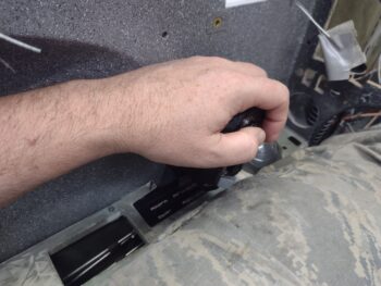
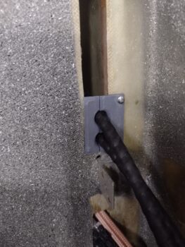
My last task of the evening in the shop (hours of CAD and 3D printing ensued afterwards) was to install my 0.03″ widened inboard GIB seatback throttle & mixture cable bulkhead pass-thru piece…. and boy was it tight.
When I got all the hardware I could the other day from a local hardware store (they have some smaller sizes: 4-40 and below), I picked up a small screw just for this install. I drilled a small pilot hole and secured the cable guide with the screw. I had planned on using flox or RTV to secure these pieces together and to the seatback, but these things are in there so TIGHTLY… and with the screw keeping them in place I’m calling this task complete.
I’m trying to get all the throttle and mixture cables and all their nitnoy associated components installed as much as I can before jumping back onto the engine: specifically the exhaust pipes. Tomorrow I plan on getting the throttle and mixture cables dialed in, and then focusing on the GIB throttle quadrant install… interspersed with getting the RAM air can install complete to the point that once the firewall covering goes on and the RAM can is bolted into place it will be operational.