
Today was a search and plan day . . . I spent a good 45 minutes searching for the other half of the my landing brake Molex connector, with no joy in finding it. And a bit of time planning & diagramming out some electrical circuits for the landing brake and various indicator lights. In addition, I printed off a fair number of labels.
Wiring up the landing brake is a strake prerequisite. Whereas the following stuff is not. However, as I was watching my friend’s daughter (my little buddy) for a few hours, it gave me something to work on while she was busy playing or watching videos.
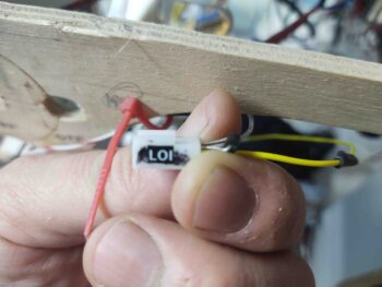
I received my order of new Korey indicator lights in the mail today, so I quickly checked those out. The top pic is the old GNS-480 GPS external annunciator light configuration, whereas the one right below it is the new light configuration. Note that “GPS” is gone, replaced by “LOI”. Also, to be more specific and more like Marco <grin> I swapped out “NAV” for “VHF NAV.”


I then verified the wiring for these indicator lights —which is still on my panel mockup with the Triparagon— and printed off nice legible labels to cover up my old Sharpie chicken-scratch labels.
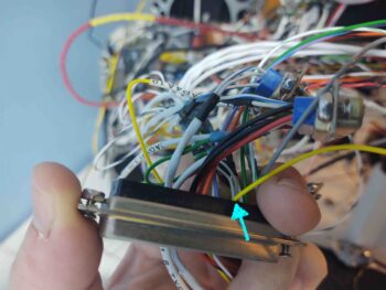
Since I was swapping the GPS indicator for the LOI indicator, I had to move the wire to a new D-Sub connector. However, since the new D-Sub is a high density one, I had to replace the standard pin with a smaller HD one. I then plugged the freshly terminated and labeled wire into its new home.
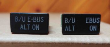
I ordered this next light a couple of years ago but it didn’t come out quite right… the one on the left. I’m trying to cheat here and create 2 indicators in the space of one indicator light. My plan is to do this by gluing a dividing wall down the center internally in the light housing and using a separate LED (and color) for each side. Thankfully this time when I ordered it they got it right… the light on the right.
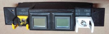
Since the switch on the right (white guard) has 3 positions:
- Top: E-Bus ON
- Middle: Back-up alternator (SD-8) field ON
- Bottom: OFF
It makes it really convenient to have an indicator for each of the ON functions.
Finally, I captured these circuit refinements and updated my wiring diagrams appropriately.