
I started off today by updating and printing out my connector pinout sheets for the following connectors:
- P4 – Throttle Handle AMP CPC
- P5 – Infinity Control Stick AMP CPC
- P6 – Panel Quick Disconnect (PQD) AMP CPC
- X-Bus – IBBS-Powered Avionics Bus 9-Pin D-Sub
- J3 – PQD Panel Power Connections 15-Pin D-Sub
- J4 – PQD Panel Signal Connections 37-Pin D-Sub
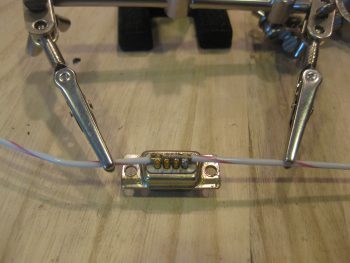
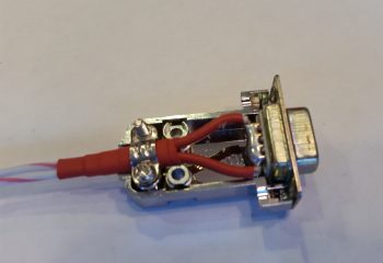
At the tail end of my updates my buddy Marco called. We talked a bit on EZ stuff, and as we spoke I got to work on soldering two 16 AWG wires to the back of a 9-Pin D-Sub connector (that I repurposed from its original role as the TruTrak ADI wiring harness).
This 9-Pin D-Sub will become the new X-Bus, replacing the original 8-slot ATC fuse holder that was the X-Bus. As per one of my very educational discussions with Bob from TCW Technologies on the IBBS install, he informed me that I don’t need to power a fuse panel since all the components powered by the IBBS must not max out past 5 amps, and the integral 10-amp mini-ATC fuse on the side of the IBBS protects these items. I had already chucked a panel-mounted switch that manually switched IBBS power to E-Bus power (EZ’er to let the IBBS to perform this standard function), and now I was eliminating more weight and complexity by swapping out the ATC fuse panel X-Bus for the new & improved 9-Pin D-Sub connector X-bus.
Now, I did originally plan on using two 18 AWG wires, but Bob advised to use 16 AWG wires. They still seem like a bit of overkill to me, so I have to admit I went 16 AWG on the other 2 wires (power & ground) that Bob intoned should be 14 AWG.
Here’s a closer shot of the two 16 AWG wires to be soldered onto the back of the 9-Pin D-Sub connector that will replace the current X-Bus.
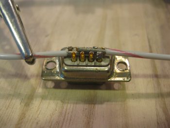
I then soldered the 16 AWG wires into place.
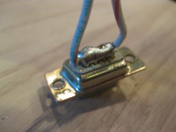
And prepped them with heat shrink . . .
Prior to mounting the wires/connector assembly in a D-Sub backshell.
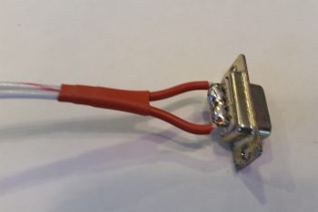
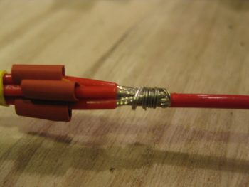
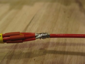
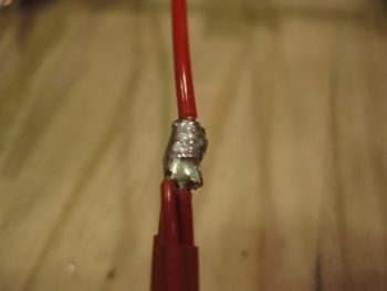
Since I want the IBBS-to-XBus circuit to have a break in it –since the wires pass through the Napster bulkhead– to allow the wires to be run without concern of the D-Sub connector getting in the way, or if unable to traverse bulkheads, I terminated the ends of the two 16 AWG X-Bus feed wires with knife splice terminals.
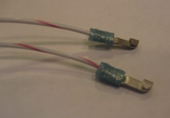
Here’s a shot of the finished X-Bus cable (A side, from IBBS).
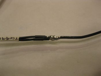
I then traced out, toned out and cut off about 9 feet of wire to trim down the four 20 AWG X-Bus feed wires coming out of the IBBS. I toned them out to ensure I had the correct wires, then terminated them into pairs, into 1 knife splice each. Thus, what I have is 4 wires exiting the IBBS unit, then those getting terminated into pairs with knife splices, then each pair connecting to a 16 AWG wire that feeds the X-Bus 9-Pin D-Sub connector (actually, the way I soldered all the pins together, it’s technically a 9-Pin D-Sub Buss).
I then turned my sights on the 3 pass-thru power wires and 1 main bus voltage sensor wire. In my discussion with Bob, he said it was perfectly ok to run these all together and fuse it with 10 amps off the main bus. So that’s exactly what I did! [Conversely, the IBBS install manual shows one fused feed to the main bus for the 3 pass-thru wires, and another fused feed for the sensor wire… always good to talk straight to the guy who designs this stuff!]
Since the other end of these 4 wires converged into one is simply a FastOn PIDG connector, I didn’t create a break in this wire group. I merely bundle them all together and slathered with hot solder!
As you can see, I did the Bob Nuckolls’ technique of making a 2-wire pigtail from the 16 AWG wire, then wrapping that around the bundle of wires so that they are all nice and tightly snug before soldering.
Here’s my IBBS 3 pass-thru power wires and bus volt sensor wire soldered to the !6 AWG wire on its way to the main bus.
I then did the same thing for the 3 ground wires that get grounded on the panel ground block (G4).
You may have noticed that some of my wire labels are hand written. There are 2 reasons for this: First, I ran out of the correct size wire label heat shrink (I’m waiting for an order to arrive), and second, I’m reclaiming some printed labels that fell victim to becoming obsolete when the new world order of PQD came into existence. I prefer to be more practical than flashy, so to save money I simply lined through the old printed label on the heat shrink piece, flipped it over and ever-so-nicely printed a new, correct label on the other side.
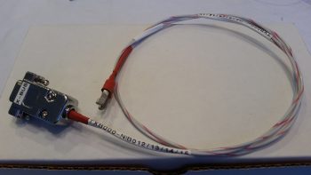
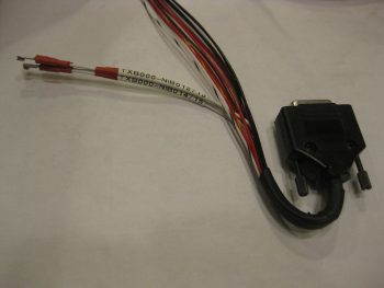
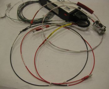
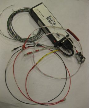
In hindsight, I should have taken a pic of the entire IBBS wiring harness before I started this process to contrast with what you see below, which is just a few random pics of the completed IBBS wiring harness.
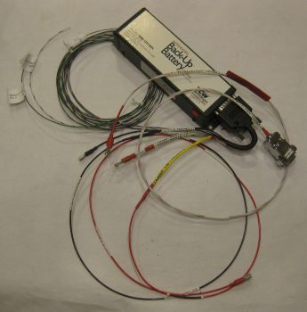
I have 3 wires out of the original 14 that did not get cut or combined:
- IBBS Master Switch (to panel switch)
- Info lead (to GRT HXr EFIS…via J4)
- IBBS Low Voltage Warning (to AG6 Warning Annunciator)
And the wires that did get cut & combined:
- 4 X-Bus Power leads into 2x 16AWG wires
- 3 Pass-thru Power wires & 1 Bus Volt Sensing wire into 1x 16AWG wire
- 3 Ground wires into 1x 16AWG wire
Among other things, this simply means that I now have half the wires to keep track of (7 vs 14) coming off the IBBS wiring harness, and fewer wires passing through the Napster bulkhead.
One final point of note. Due to how the IBBS box is mount vertically on the front left face of Napster, as the wires in the harness exit the IBBS D-Sub connector they must immediately make a U-Turn to get keep from dragging on the floor of the nose battery compartment. One of my first tasks tonight was to place a large piece of black heat shrink over all the wires in the harness. Then before applying heat, I zip-tied the harness back onto itself in a “U” shape. I then heat up & shrank the tubing and it kept its “U” shape perfectly. Pretty cool!
Tomorrow I’ll continue to work on both the Triparagon & the wiring in/about the avionics bay.