
Today I started out by finishing up the lightening holes on the Triparagon cross shelf. I drilled small 3/8″ holes in literally every spot that there was space to, again to get this thing as light as possible without compromising strength. I removed the PQD bracket to drill lightening holes on the cross shelf above where the bracket mounts.
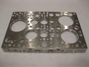
After drilling the last of the lightening holes, I then spent a good hour and a half deburring the holes and cleaning up the cross shelf. I still need to finalize the deburring, but I at least got the rough stuff off the hole edges.
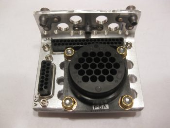
I also drilled lightening holes in the PQD bracket, which again I need to finalizing the deburring on those holes as well. I then mounted the P6, J3 and J4 connectors.
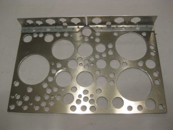
Here’s another view from the top.
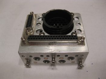
And an aft bracket view (technically a forward view).
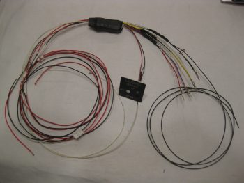
I then spent a couple of hours prepping my Jack Wilhelmson Landing Brake wiring harness. Below you can see the included switch panel for mounting the switch and LED lights to the instrument panel. I removed that switch since I replaced it with the switch in the throttle handle to control the Landing Brake, which means that the wiring goes through the P4 connector.
The majority of time I spent working on this bad boy wasn’t the actual physical wiring stuff, but in tracking down, confirming & verifying what wires went where to label them correctly. Again, since I’m utilizing connectors now in my electrical system wiring scheme, much of my previous A → B wiring is now A → ⊗ | ⊗ → B where ⊗ is the connector. Since many of my wire labels are now outdated, I simply crossed out the old label with a Sharpie and rewrote the new labels by hand to use up my stock of “bad” labels on this wiring harness.
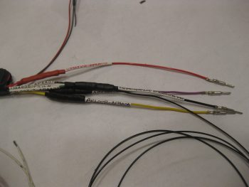
Since the wires coming out of the relay decks were too short to comfortably terminate into the P4 connector, I had to extend these wires. Instead of soldering them, I went the lazy route this time around and simply used butt connectors. I then used heat shrink over the crimped butt connectors. As you can see, I finished labeling all these harness wires, and then crimped AMP CPC pins on the ends of the 4 Landing Brake wires that will get terminated into the P4 connector.
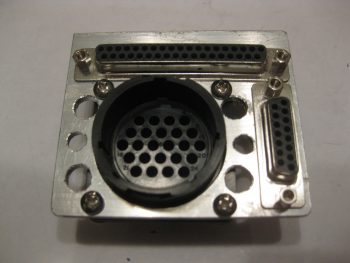
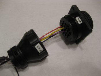
Here are the 4 Landing Brake wires terminated into the P4 connector. Note that I slipped the cable clamp into place before terminating the wires.
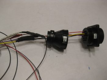
A closer shot of the Landing Brake wires in the P4 connector (A side).
Tomorrow I’ll press forward on the Triparagon and the avionics bay wiring.