
I started off today with the intent to finish the edging on the lightening holes on the Triparagon cross shelf. But that didn’t happen.
What did happen was I did a test fit of the IBBS & it’s ‘new & improved’ wiring harness. Part of that test fit was to ensure that ALL the wires –not just the IBBS wires– fit through the hole & protective grommet that traverses the Napster bulkhead. And, as per usual, since I just happened to be in the neighbor hood, I figured I couldn’t really test if the wires fit unless the actual wires (and cables) that will run through this transit hole are used in the test.
So I decided to go ahead and get the landing landing light and taxi light wiring/cabling knocked out.
First up was the landing light. The installation manual for the AeroLEDs Sunray Plus landing light calls for using 20 AWG shielded wiring to power the light. I only had 22 AWG on hand, so I used it since I’m confident that it will work since the actual run is only about 5 ft vs 3-5 longer than that if it was buried out at the end of a wing somewhere in a “typical” install.
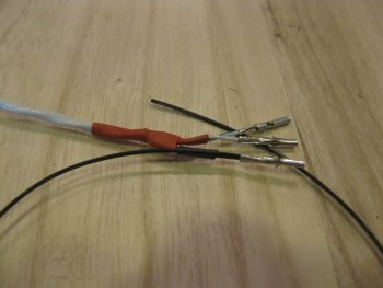
I started by stripping away about 2″ of the outer jacket.
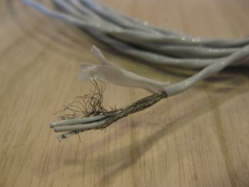
I then wrangled and cut the shielding wire.
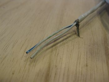
And soldered a piece of 22AWG black wire for the ground wire.
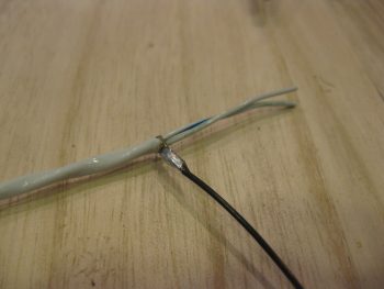
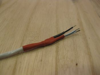
I then heat shrinked it all up: red to symbolize positive power, and black for the negative ground wire.
I then terminated the wire ends with mini-Molex socket connectors. Note that the black pigtail wire will actually terminated on a mini ground tabs block that I’ll have mounted onto the negative post of the battery. [Note: Although I’m not a fan of Molex connectors for the larger, multi-pinned connectors, the mini-Molex connectors work just fine for 2-6 wire applications … just my opinion, YMMV].
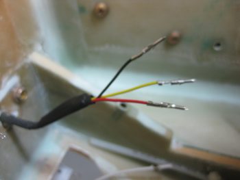
I then prepped the landing light side. I had 2 extra wires that I simply folded back onto the main cable and heat shrinked in place. I then terminated the remaining 3 active wires (red for light power, black for ground, yellow for wig-wag) with mini-Molex pin connectors.
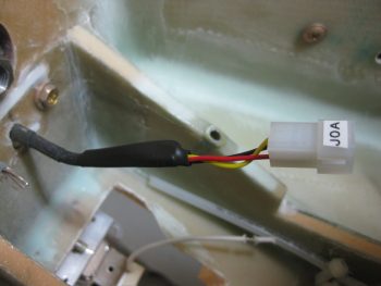
And then attached the 4-pin mini-Molex connector (J0, A side).
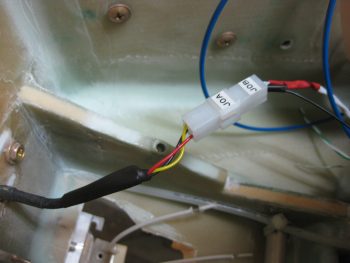
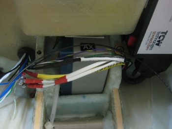
After running the landing light cable through the hole & grommet in Napster, I then connected the J0B side of the landing light connector to the J0A side. Looking good! Note in the pic above and below the white wire leads of the taxi light, those will change in a bit.
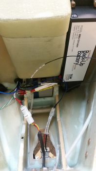
I had previously installed the IBBS to test its fit. As a side note, after some investigation I realized that the end of the IBBS box cover (that has the “IB” label attached) was bowed out a bit & thus not allowing me to use normal sized AN3 nuts. So I removed the IBBS cover, gently pressed the end back straight, reattached it and . . . Voila! It mounts perfectly!
Back to the wiring… Get this: to get all the wires to fit, I actually have to removed the grommet out of the lower wire transit hole in Napster, then push the 2 knife splices through, then the PIDG FastOn connectors for the IBSS power & ground wires, then reinsert the grommet before the rest of the wires can go through. Also, I can’t terminate OR LABEL any more wires at this time if they are going to fit through that hole…. VERY TIGHT FIT! Which is good because of course it keeps the wires secure. It also gave me a chance to try out my “Wire Spoon” that I picked up from Stein a million years ago and have never used. Works great and really does allow you to insert wires through the hole in the midst of a big wire bundle that you would otherwise not be able to get in there.
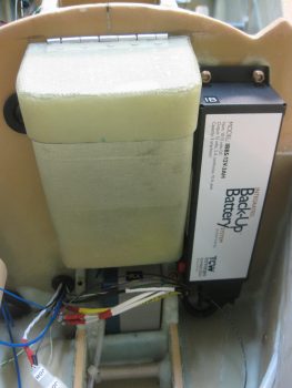
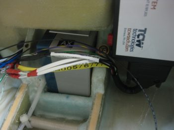
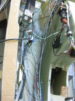
The next couple of shots are simply closeups of the IBBS wiring harness crossing over the nose gear back up battery, just underneath the nose tool box, and exiting out of the nose through the lower hole in Napster. (You get a better shot of the IBBS harness “U-Turn” in pic #2).
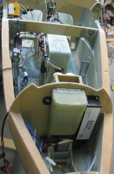
Here’s a long view of “Electron Alley” showing the myriad of wires that are currently in play and that I’m contending with.
I then set to work to terminate and wire up the Taxi Light with a 22 AWG blue wire for power (blue just happens to be the color of the wires used in the Infinity stick grip for that switch, so I carried that color all the way through) and a 22 AWG black wire for ground. Note that I also labeled the wires on the light side, something I didn’t have space to do on the landing light. I finished off the installation using a 2-pin mini-Molex connector (J7) that I bought well over a year ago specifically for the taxi light connection.
Here’s a closer shot of ‘Electron Alley’ . . .
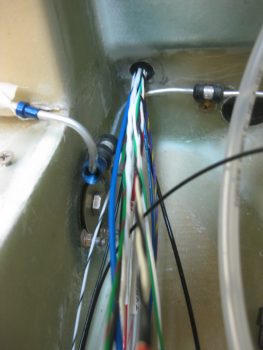
And a shot of the lower wire transit hole in Napster from the aft side. The wires you see are currently all the wires that I plan on having transit through this hole (yes, things can change, thus the emphasis on the word “currently”!).
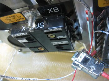
I also wanted to get a pic of the old ATC fuse block X-Bus (left) compared to the new 9-Pin D-Sub X-Bus (right). As I pointed out before, this modification will save space, weight and complexity (e.g. no individual fuses).
I was heading out to dinner with a buddy of mine, but before I ran out I wanted to get one more thing finished for the evening: widen the lower left hole in the instrument panel bulkhead to allow the P4 connector, which was just a tad too big (note the black markings on the sides of the hole) to fit. I used a sanding drum on my drilled, fired up my shop vac and went to work.
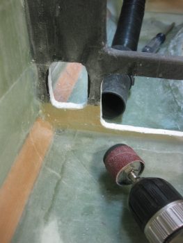
Less than a minute later . . . Voila! Now the P4 connector just fits through the hole! My next step will be to add an Adel clamp to keep the throttle handle cable secure. I would like to reiterate my ongoing theme here by pointing out that this is the type of stuff I really want to get figured out before I close up the nose, while I have infinitely much more access to work on it all.

Tomorrow I’ll continue on with my push to knock out the avionics area electrical stuff, as well as get the Triparagon install finished. (Then, on to the wheel pants!)