A ‘funny’ thing happened to me this morning: Analysis Paralysis! There is literally SO much to do on getting the interior components and electrical systems emplaced in the nose, that I found myself in the weeds, overwhelmed in which actual direction to charge off into… too many moving parts going on right now!
I decided to focus on getting all the aluminum parts cut that I will need in the near future, and specifically focus on one of the critical completion items on my list before I can move forward with closing up the nose: the actuator assembly install for my Atkinson pitch trim system.
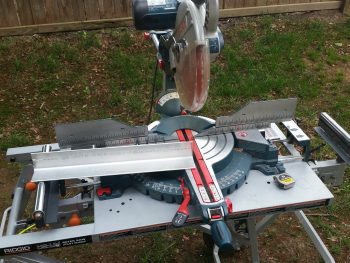
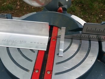
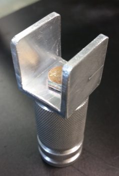
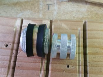
I just got some more 1/8″-thick-sided (1″x1″ overall) 6061 U-channel in from ACS that I ordered earlier this week. I pulled out the big saw and cut the U-channel 1″ wide to match the diameter of the knurled pitch trim actuator installation hard-point that Marco machined for me (shown below); another fresh bracket lever arm piece for the taxi light actuator (shown getting cut below); a narrow piece of 1/8″ thick 2024 for the other taxi light lever arm; and finally, a somewhat “D” shaped rotating bracket that is the actual attach point for the pitch trim actuator… which gets installed inside the U-channel cut above (all this is shown below as well).
Again, as you can see, these pics show me cutting the bracket lever arm piece for the taxi light actuator.
Here’s the U-channel bracket that attaches to the knurled pitch trim actuator installation hard-point. I ended up scrapping this one and making another one with the locations of both sets of mounting holes dialed in to better fit the tight installation requirements.
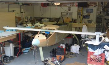
Of course, to figure out the exact installation configuration of the pitch trim actuator, I needed to reinstall the canard.
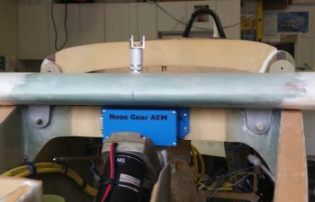
I quickly collected up yet another Marco-made item (thanks Brother!), the Nose Gear AEM box to verify that my dimensions were correct so that it fit in place with the canard installed, and it does.
Beyond reconnecting the elevator control tube I also verified clearance between the elevator control arm and the big power cables mounted just below it to the side wall. Again, plenty of clearance with the elevator control arm at its lowest point.
Alas, after spending a fair amount of time dialing in the installation configuration and location for the pitch trim actuator, I finally came to the point where I had to sadly cut Marco’s beautifully machined hard point creation in half. The side wall where this thing will get installed is simply much narrower than the length of this insert. I would have chosen to keep the lathed flox grooves on the aft side, but since he could only get the 1/4-28 thread tapped down about 3/4″ of the way into the bolt hole, I did’t want to risk not having enough threads left for a bolt to really bite into. So, I mounted it into a tight-fitting Adel clamp and carefully cut it on the big saw.
I then spent a good hour+ measuring, drilling, filing, sanding, and finalizing the interior pivot bracket & external mounting bracket that physically attaches the pitch trim actuator to the side wall hard-point mount.
You may have seen that in installations on other builders’ projects that this actuator simple gets mounted with the actuator motor oriented vertically, either up or down. Unfortunately, if I went actuator motor up, I would need to glass in a bump on my nose to clear it. If I mounted it actuator motor down, then I would have to contend with it interfering with my right foot while working the rudder/brake pedal. This all becomes paramount with the understanding that the actuator must be able to pivot side-to-side so that the other end of the pitch trim assembly, which is mounted to the elevator control tube, is allowed to freely pivot with the left-right movement of the control stick.
Thus, I note all this because of the way the physical mounting tab is situated on the pitch trim actuator, in its comparative ease of being mounted vertically, either up or down, which allows for the required side-to-side pivoting action. However, once mounted with the motor positioned horizontally you could easily realize an up-down pivot action –which isn’t needed or wanted– but not the required side-to-side motion. Obviously then, I had to account for the actuator mounting tab’s configuration with an intermediate bracket that provides this required side-to-side motion for the now “incorrectly” mounted actuator.
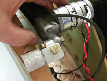
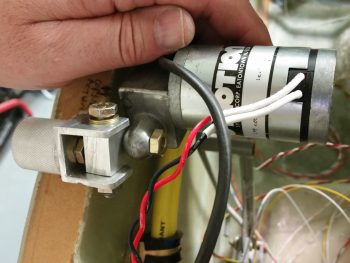
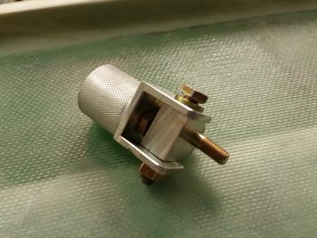
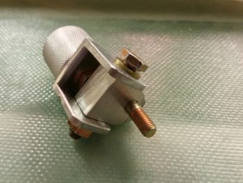
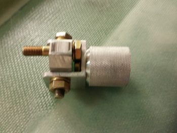
Here’s another shot of the pitch trim mounting bracket assembly.
I then detached the pitch trim mounting bracket assembly from the actuator motor mounting tab and snapped a few shots of it at different angles.
I still need to fine tune the fit & finish of the individual parts, but as you can see, the main configuration design is complete. And I haven’t noted anything thus far that will preclude this from working as designed.
I’d like to finalize the pitch trim install over the weekend, and move on to other interior nose-located items in prep for closing up the nose.

