
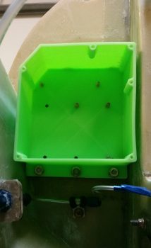
I didn’t get the intermediate steps documented since I’ve been out & about this weekend with friends. Here is the final result of the Clickbond mounting for the Nose Gear RCU box. Again, I used 3 plies of BID along the top row (2 Clickbonds) . . .
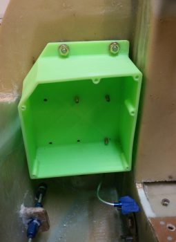
. . . and 3 plies of BID along the bottom row (3 Clickbonds). After curing, I pulled the peel ply and cleaned up the goobers. Thus, the RCU box is officially mounted.
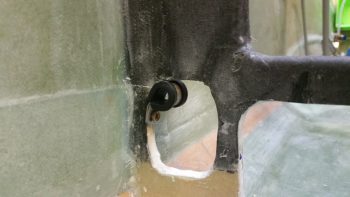
A little sideline tasker I completed was to drill and flox in place this Adel clamp for the Throttle electronics cable that terminates into the P4 Connector.
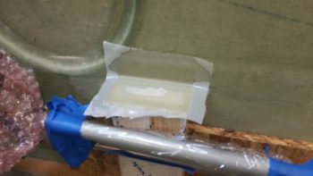
After pre-drilling the 4 screw holes and the 8 holes for the K1000-6 nutplates, I then did a final trim & sanding on the Dynon Intercom bracket. I determined where its position needed to be and marked the sidewall. I then 5-min glued the intercom bracket to the sidewall.
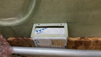
I then laid up 2 plies of BID (pre-pregged of course!) on the top side of the intercom bracket, and peel plied it.
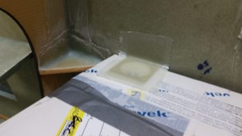
I pretty much followed the same steps for the Throttle handle electronics cable P4 connector bracket just forward of the instrument panel on the left side. After 5-min glueing it to the wall, I laid up 2-plies of BID and peel plied it.
These tasks above are all on a list of 10 electrically-related items that I want to have finished before I move on to the wheel pants. Once these brackets and the RCU box wiring are completed, I’ll be down to about a half-dozen items on the list.