
Today was the Big Reveal day for the taxi light cover. Since my layup was practicing the truest form of accelerated entropy last night, I simply covered it with Saran wrap and taped it up profusely! This morning I took off the long cross pieces of tape that I used to keep the whole layup from squeezing up the sides of the taped form, really making the cover unusable if it had. I was now at the precipice of finding out what I had underneath of all this tape. Would it be usable? Would have I have to start all over again from square zero?Let’s find out . . .
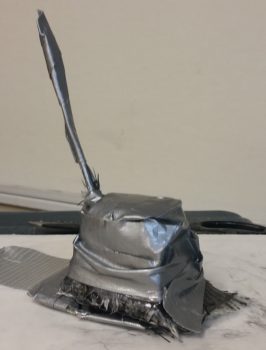
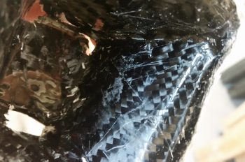
Ok, so here’s the result in Airdog’s crazy layup experiment emporium. Quite an interesting specimen I’d say, but it really does look usable. As I’ve mentioned many times before, so much of these one-off custom jobs are ITERATIVE processes!
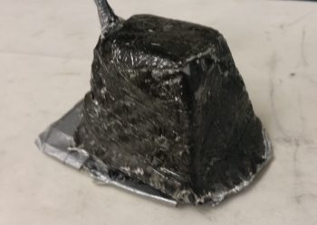
I grabbed my sanding block and my Perm-A-Grit tools and went to town on the taxi light cover. I knew that I would most likely create some holes in this cover to get the shape worked out correctly . . . and I was right. It is interesting that the resulting pics all look quite a bit like snake skin.

Here’s the opposite side. It may be a bit difficult to see, but because I taped the top of the cover down, it resulted in 2 actions: One negative, and one ok. The negative action was that it created “shoulders” on each side of the cover just below the top. My plan was to cut these off and layup a ply of BID that will bridge across the resulting hole. The squashing of the top resulted in the 2nd action, which was that it pushed the sides just below the “shoulders” inboard more…. which was fine and actually allowed for a tighter fitting cover (i.e. takes up less room).
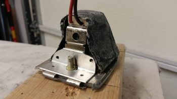
Here’s the sanded taxi light cover next to the taped up taxi light that I used as the cover form.
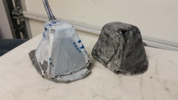
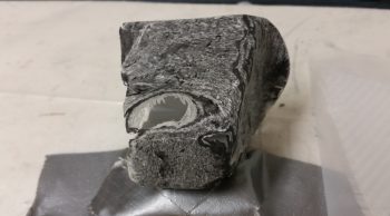
Also, here’s a shot of the inside of the taxi light cover. Aside from scratches from the scribe I used to pry the cover off, the carbon fiber really looks nice. Overall, this pic again has a snakeskin look to it (Marco also pointed this out when he saw it).
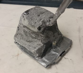
After assessing the cover’s usability –including cover mounting & removal– I decided that because the lips on each side clamp around the flanged base of the taxi light bulb mounting assembly, that I it was not practical to keep the forward side of the cover in place. I cut off the forward face of the cover to simply allow the cover to be slid on from the bottom (if it’s deployed/out) or aft (retracted) side of the taxi light. After testing this configuration I could tell immediately that I had made the right call on removing the forward cover side. Much easier!
I then prepped it for more glass (repair layup, if you will . . .) by sanding it to shape. This prep also included using the Fein Saw to remove the right “shoulder” just below the cover top, which left a decent-sized hole in the cover.
To keep this story line flowing, I’m jumping ahead here with my pics. The pic below is exactly what I did above, but on the cover’s left side. The yellow epoxy spreader is being employed as a form weight to keep the overhanging glass flat against the side lip. Besides wrapping around the taxi light bulb mounting base to keep the cover securely in place, this side lip will get drilled in 2 places, and be held in place with two 4-40 screws.

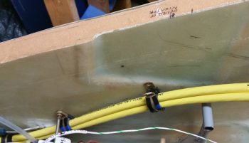
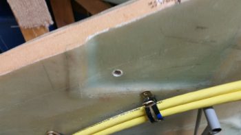
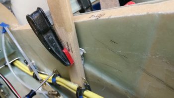
In addition to the taxi light cover, I continued to work on securing the 2 big power cables (one + power and the other – ground) that start in the nose battery compartment and end at the firewall & starter, respectively. Again, I had to reroute these cables up and over my rudder pedal (you can see in the pic how they get in the way if not wrangled) in an arch/ Bell curve fashion. With the 1st added Adel clamp in place, I marked the position for the 2nd additional Adel clamp. Note in the upper right hand corner of the pic my markings for the Atkinson pitch trim actuator mounting. You can see that I need to get these power cables as high up on the nose sidewall as possible, but still remain clear of the pitch trim actuator mounting.
After marking the spot, I then drilled the hole in the nose sidewall. This area was a bit tougher to drill since, if you recall, that indented area that this hole was placed has additional plies of BID to beef it up for the mounting of the pitch trim actuator.
I then performed the “poor man’s” knurling of the 10-32 threaded aluminum insert that will be used to mount the Adel clamp in this location. I wanted to use this threaded insert since it’s a bit more robust than a RivNut.
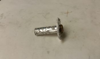
I then whipped up some flox and mounted the threaded insert assembly (including a taped washer mounted to it with an AN3 bolt). I then clamped it in place to ensure it would be level with the surrounding sidewall surface when it cured.
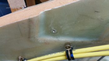
Here’s a shot about 10 hours later after it cured to about 80-90%. The flox was still just barely soft enough to be easily removed with a razor blade (there was an entire ring of it around the perimeter of the taped washer).
Although it’s a bit slow going, I am getting through all the electrical related taskers on my list. I expect about another week, maybe 2 at the most, before I’m ready to get back to the big chapter build items again.