
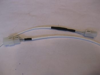
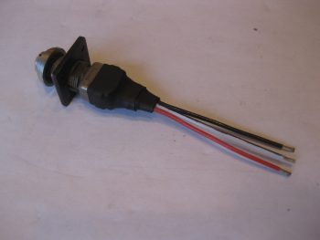
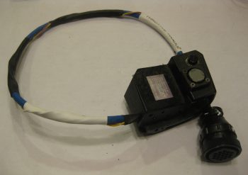
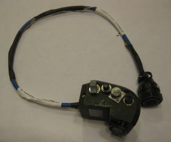
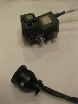
As I was finalizing my last blog post the doorbell rang. It was my mailman delivering my order from Stein, so after I finished up my blog post I opened up the box to check out all the goodies. I took the 6-pin mini-Molex and quickly mounted the B-side to the roll trim cable. I already had labels made up so I quickly labeled both sides of the J5 jack as well. (As a reminder, my labeling scheme for connectors is quite simple: the “A” means it’s closer to the nose while “B” means tail side. If the connector or jack is vertical, then the hard mounted side is “A” and the removal side is “B”).
I then took a few minutes to prep the fuselage for me to sit in it and make some airplane noises. I needed to figure out where my Dynon intercom box is going to call home, so I pulled the wood blocks out from under the nose wheel, cleaned the tools and extraneous components out of the front seat and climbed in. I discovered that I can reach back and manipulate the controls of the intercom if it’s against the right fuselage sidewall, just aft of the stick. How about 2″ aft of the stick? … uh, nope, not really. Too difficult there. But half an inch back I can curl my hand down comfortably and work the intercom controls.
I like this position because it’s really unclaimed, unused real estate that can be put to good use. Also, I’ve had my eye on the left armrest area just forward of the throttle quadrant to use for my environmental controls panel. Now that I’ve decided to put the Dynon intercom on the right armrest console just aft of the stick I can reclaim the forward left armrest console for the environment controls!
In addition, in thinking about where my intercom control head would go, I naturally wondered where I was going to put my headset jacks. I’ve discussed this with Marco in the past, and we had yet another quick exchange about it via text. I really wanted to keep the headphone jacks off the panel, but where to put them? After doing a bit of research last night, I would like to give a shout out to Nate Mullins –and in turn, James Redmon– for highlighting the very aft side of the armrest for being a good location. Now, they picked the aft side of the left armrest to mount their jacks, but I’m leaning towards the right for 3 reasons:
- It keeps the headset wires on the right side of the seat when ingressing/egressing the aircraft.
- It keeps the electrical wires on the right side of the aircraft (power wires right, antenna cables left), and
- It keeps the shielded wire run betwixt intercom box and jack very short, and since this specific wire run is the most susceptible to gremlins and things that go staticky in the night, I would rather keep it as short (aka noise free) as possible.
So that’s 2 fairly significant component placement decisions that I made today…. after literally years of those questions floating around in the recesses of my mind.
Ok, on to the task at hand: wiring the throttle handle.
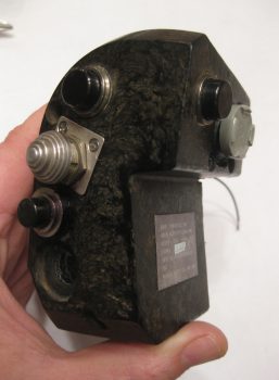
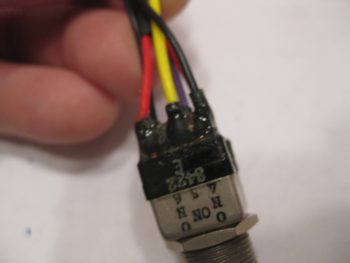
While down in the shop I collected up my throttle-handle-mounted nose gear switch that I had gooped up the aft end of with E6000 to secure the wires both to each other and to the switch body. Since these switches are older (but still look in great shape) and I had to wrangle off the massive amounts of old wiring, I want to make sure both the solder connections and switch connecting tabs stay secure, and are subjected to as little vibration as possible.
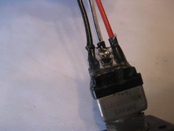
Here’s another shot of the E6000 gooped-up nose gear switch.
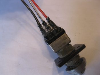
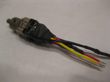
To finalize my wire-securing process on the nose gear switch, I added 2 pieces of heat shrink around the base of the wires and goop.
I then added a piece of heat shrink that secured the wire/goop subassembly to the body of the switch.
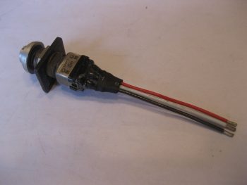
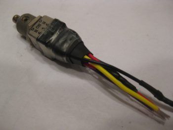
I had to run down to my favorite hardware store to pick up a 2-56 stainless steel CS screw since I apparently lost one of the nose gear switch’s mounting screw somewhere. I test fitted the screws, took it back apart and then judiciously used some E6000 on the screws and around the base of the switch mount before permanently remounting the nose gear switch into place on the throttle handle.
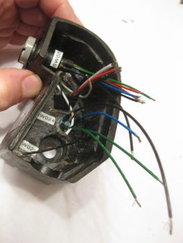
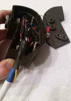
Here’s how the developing rat’s nest of wires looked after I added the nose gear switch.
I should note that before I ran out to get the missing 2-56 screw (try finding one of those when you don’t know where it ran off to!) I gooped up the wires/switch intersection of the landing brake switch with E6000. Here are a couple of slightly fuzzy pics to show you how it looked when it cured.
I then repeated the heat shrink process on the wire/goop area of the landing brake switch.
Then secured it to the switch body with a clear piece of heat shrink.
I then installed the bottom and last switch for the landing brake into the throttle handle.
At this point it was time to start connecting all the throttle handle switches’ wire leads to the blue cable. I spent a good 3 hours soldering all the switch lead wires to the blue cable harness wires. I had already identified which wires in the blue cable were 22 AWG and which ones were 20 AWG, and had to account for this when wiring up the switches. I did only 2-3 wires at a time, ensured they toned out, then added heat shrink (that I had to ensure was on the wires before I started soldering) over the solder joint before moving onto the next few wires.
Then it was time to start cramming… wires that is. There was actually enough room in the throttle handle housing to stuff all the wires back into it comfortably. As you can see I reclaimed one of the ring connectors from the original harness and pigtailed it off the ground wire for ground to the throttle handle housing. You can also see that in this and subsequent pics that I finalized securing the two extra 18 AWG wires spiraled about the blue cable. I also labeled the cable and added lengths of heat shrink to secure the two 18 AWG wires.
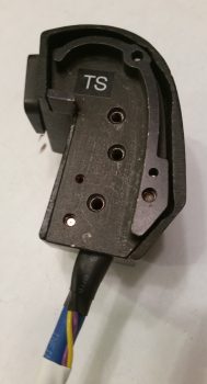
I then remounted the throttle handle side plate cover with the 3 original screws.
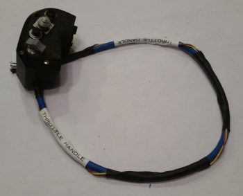
Here’s a shot of the throttle handle with all the switches rewired & remounted and the cable prepped for having an AMP CPC connector terminated onto it.
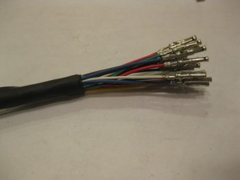
I then terminated all the wires with AMP CPC connector sockets.
Since I had NOT actually created the pinout scheme for the P4 connector, I stopped work and spent a good 45 minutes determining the pinouts for this connector. Once done, I toned out the wires to ensure both continuity and to check wire IDs since there were multiple wires for each color (e.g. lots of red & black wires). As I determined what wire was what I then placed them into their appropriate numbered socket hole.
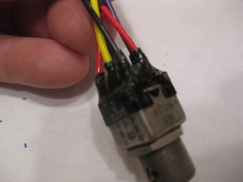
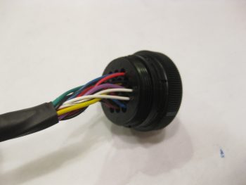
Here’s a closer shot of the throttle handle switch wiring terminated into the AMP CPC connector housing.
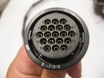
And here’s a shot of the front face of the P4 (B-side) AMP CPC connector.
I then secured the wires with silicon rubber self-sealing tape before finalizing the cable clamp install.
I then mounted the cable clamp to finish the throttle handle cable.
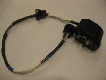
Here’s a shot of the full length throttle handle cable.
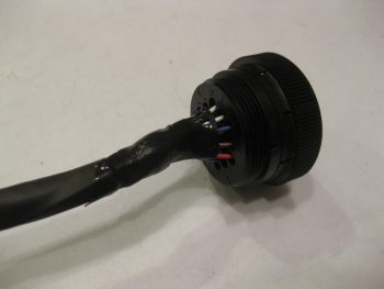
And a final shot of the throttle handle and P4 connector.
Tomorrow I’ll be back working in the avionics bay, both on getting Adel clamp hard points installed and finishing up the Triparagon.