
This post covers today and yesterday since I was remiss in posting yesterday. This weekend has been a busy one both socially and of course with football (yes, I’m an avowed football junky!).
Ya’ll have probably noticed that as I work on any one component, I like to knock out those components directly around it since I’m already “in the groove,” plus it gets those items finished. In addition, I already know how they fit into the area that I’m working. I understand that my build methodology is somewhat organic, and often unscripted, but staying motivated and simply getting many productive hours in on the build a day is the key to having an airplane sitting on the ramp vs a project in your garage, right?!
And so it is with my electrical system. There are a myriad of low hanging fruits right now that I’m simply going to knock out: changing as many variables into constants and resolving as many unknowns as I can at this point in the build.
Thus, it is that one of those low hanging fruits right now is the throttle handle. As I’ve stated before, especially in an airplane as space constrained as a Long-EZ, I am a total believer in maximizing the HOTAS (Hands on Throttle and Stick) concept as much as possible. If it’s good enough for task-saturated military fighter pilots, it should work fairly well for us too.
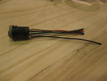
I started off yesterday by determining my wiring gage requirements for the throttle switches. I then assessed the 17 wires in the 2+ ft of leftover blue cable that I cut off the Infinity stick grip. After listing out all the wires and gages, I determined that I could I repurpose this leftover blue cable for the throttle handle switches. Since there’s only 17 wires in the cable, I’ll also run two 18 AWG wires for the landing brake along the outside of the blue cable, for a total of 19 wires to the P4 AMP CPC connector.
I then got to work widening the mounting hole diameter for my 5-way castle switch (“joystick”) that controls a few A → B options on the GPS (i.e. GPS to VLOC) or page/screen scrolling functions (Trio fuel screens, GRT screen flips, etc).
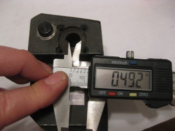
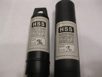
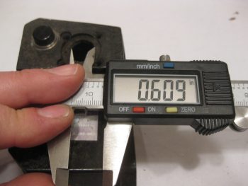
A few months ago I picked up these drill bits specifically for this task: the 39/64″ bit to drill out the majority of the hole diameter, then the 19/32″ bit to fine tune the hole size.
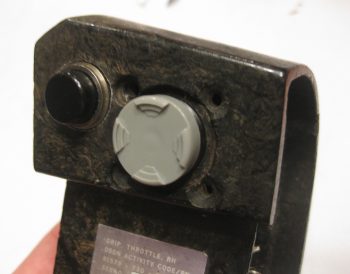
Here’s the hole post drilling, ready for the 5-position switch.
The switch has a plastic keyway on the side for positioning. Of course I could have removed it, but I decided to leave it in place and notch the side of the hole. I clocked the switch position so that not only are the finger grips in the 3-6-9-12 O’clock positions, but also so that the ground connector tab was closest to the backside handle opening.
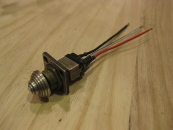
After notching the hole for the switch’s keyway, I then test fitted the switch. So far I’m very happy with how this switch is working out!
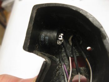
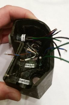
Here’s an inside-handle shot of the 5-way switch, with the ground connector tab on the aft side of the switch closest to the handle opening.
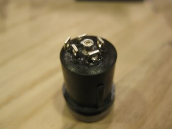
Here’s a shot of the back side of the 5-position switch. Note that the ground tab is the tab on the far left, away from the center 5 tabs..
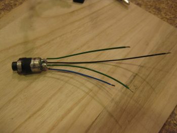
I then cut, stripped & soldered the 5 switch position wires and the ground wire onto the tabs on the backside of the 5-position switch.
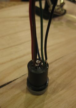
Another shot of the wires soldered onto the 5-position switch.
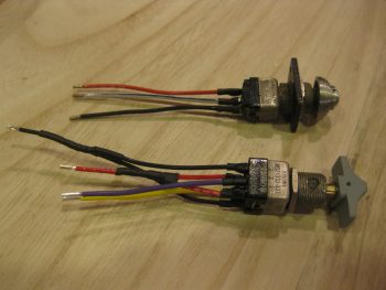
On the 2 other top mounted throttle push button switches… since I couldn’t get these switches out of the throttle handle without destroying or marring them greatly, I simply used the wires that were attached to the switches and soldered them to the identified wires in the leftover blue cable that I cut off the Infinity stick grip.
Well, after getting these 2 switches wires soldered to the blue cable wires, I then toned them out for continuity. When I check continuity on my Fluke multimeter, I generally just check for sound and call it good. But this time I actually caught sight of the resistance reading, which was on the order of 6 & 9 ohms for the respective switches. Whoa, pretty high resistance for basic momentary push button switches, what was going on? Well, under closer inspection I realized that the heat shrink over the wires at the switches wasn’t just wires, there were resistors in line as as well. Of course I don’t need resistors for these 2 switches, so they had to go.
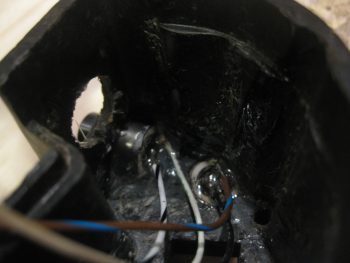
After I removed the offending resistors, then the issue became soldering the switch leads onto the switch posts down in the very depths of the throttle handle housing. Hmmm, I’m decent at soldering, but this proved to be a bit challenging. I did it, but my confidence in the physical strength of the solder joints wasn’t as high to my liking, so I did what any responsible builder would do, I reinforced those solder joints by burying them in potting goop! After testing the switches electrical continuity (good) and checking that the resistance was back down into the normal range (0.2Ω), I then used E6000 to cover up the freshly soldered switch lead wire joints.
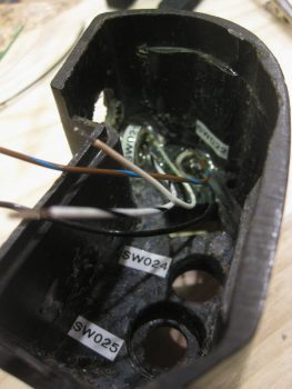
I went ahead and ran a strip of labels and printed off a few to label the switches on the inside of the throttle handle.
I then got to work on the SW024, the transponder Ident button & SmartStart arming switch. I cleaned up the switch wire tabs and soldered the correct colored wires to the tabs.
I then mounted the 5-position switch (SW020) and remounted the transponder Ident & SmartStart arming switch (SW024) into the throttle handle using RTV silicone, and set it aside to cure.
As the 2 freshly added throttle handle switches cured, I then got to work on the nose gear UP & DOWN switch. Again, I verified the correct size and colors of the wires, then soldered them into place.
I then finished off the mojamma of the throttle handles switches, the landing brake switch with its multiple cross-pairs of wires.
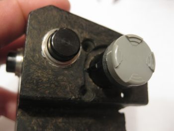
Here’s a shot of the day’s tasks, with a total of 4 out of the 6 switches installed.
Tomorrow I’ll install the last 2 switches and finalize the wiring on the throttle cable, to include termination the blue cable into the P4 AMP CPC connector (B side).