
Over the past couple of days I’ve had a heavy social calendar with old friends wanting to get together, which is always great. On Friday and Saturday I squeezed in maybe 45 minutes each day to work on updating my electrical system diagrams, starting with my connector pinout sheets.
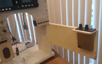
Today (Sunday) I started off making a bit of noise by cutting a 19.5″ long x 6″ high arm to mount to the right side of the instrument panel mockup base to allow me to mount the intercom very close relationally to where it resides in the actual aircraft. Although this intercom is small in size, the whole aft end is nothing but a D-Sub connector and there are a lot of cross connections required from the panel components.
With my requisite construction task out of the way, I then started in on what I’ve been trying to get to for the past couple of days: my electrical system diagrams. One way I keep track of all my connectors is that AMP CPC connector ID codes start with “P” (“plug”) while D-Sub and mini-Molex connectors start with “J” (“jack’). This scheme also gives me more numbers on hand for each series, since there are a fair number of distinct connectors in this airplane.
Well, besides the myriad of other updates I needed to do, including finalizing the switch out of circuits coming off the big 24-pin P6 PQD connector, I also created a new 4-pin AMP CPC plug (P7) for the GRT HXr power wires. Concurrently, I reclaimed its previous J10 tagline for the 25-pin Audio Mixer D-Sub connector.
Finally, if a connector is merely planned and has not been fully pressed into use, I may switch them around in an effort to keep the numbering scheme so that the low numbers start at the nose and get bigger as they move towards the back of the plane (i.e. J1 towards nose, J12 in hell hole, for example). Well, I stole the P7 moniker from the Trio roll servo that resides in the engine compartment and its new label is now P8. This of course required physically removing labels and adding new ones. A bit of a mundane task in doing all this, but in the end I feel wholly worth it in having a well organized, more easily maintainable, electrical system.
With the reallocation shell game complete, I then went to work updating my connector pinout diagram sheets. After those were complete, I then did a 100% review and update of all my electrical system diagrams. I added the 6 new GNS480 external annunciators to the panel diagram (#1) and tweaked all the other diagrams as well.
One major difference in my updates this time around, on a number of occasions I noted exactly how long a certain wire was that was included by the manufacturer on their wiring harness, and then approximated how much more I needed to add to complete the physical wire run. For example, on ElectroAir’s EIS Controller, that will sit in the GIB headrest, the main 20 AWG yellow wire that runs forward to the EI (“mag”) switch on the console is 6 feet long coming off the EIS Controller’s wiring harness. Not long enough to reach the front, so I annotated that on the wiring diagram. Now I know to have or reserve some 20 AWG yellow wire to extend the EIS Controller switch wire.
Beyond that, a lot of my diagrams were simply the old versions with my chicken scratch notes annotated on them, while the electronic versions were up to date. I took the time to verify the info was correct, updated other info as need be, and printed off a fresh copy of every electrical diagram. I’m sure I’ll need to do this a another few times before the plane is finished, but as of now I have a really good baseline for my entire electrical system being up to date.
As for the actual build, I’m waiting for the CAMLOC receptacle that I ordered from ACS to arrive before I press forward with the pilot seat thigh support installation, and then the subsequent tasks that follow. I also made some other minor orders for some now known USB cable lengths and avionics panel mounting hardware. Thus, in the next few days, until the CAMLOC receptacle arrives, I will take the opportunity to focus on getting the panel wired up.