I actually started off today pulling peel ply and doing a rough cleanup on left armrest layup. I did a bit more thorough trimming later on in the pics below.
Then I started in on my cupholder. I realize, without the plane being close to flying, that folks may wonder why I’m focusing on some things that seem rather insignificant in the grand scheme of things, especially in regards to getting this plane in the air. I have to say that is quite often the mantra I hear either online or from other builders in person: “Just get ‘er in the air, all that other stuff will come later!”
Well, if you’ve been reading this blog for any amount of time you’ll know that I respectfully disagree, because in my mind what we’re building here is a system. How often a $3 part is the one thing that keeps you from using a household appliance? So, if I am to finish the left side armrest, I must know how ALL the pieces are going to fit inside it… you can really see how every new area becomes a puzzle with the goal to make all the pieces fit.
Having heard stories and seeing firsthand what a pain is to keep a bottle of water at the ready for some hydration during a 3 hour trip, and not tucked away in a spot where although you can feel the nice cold bottle pressed against you, alas, you know that you’re not going to drink anything until that plane is on the ground. The bottom line is that Long-EZs are not Cessna 172s, and to get all the good out of them we must accept some of less than stellar characteristics of the design: as in NO space to put stuff.
Ok, off my soap box.
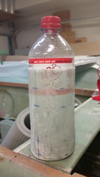
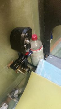
Here’s the cupholder with your typical soda bottle inside it. Water bottles are most often narrower than this.
The cupholder will sit immediately in front of the throttle quadrant, which is really the only place I could place this nearly full armrest height component given that the throttle quadrant must have clearance aft of it for the throttle and mixture cables to head rearward into the engine compartment.
However, immediately forward of the cup holder for a good 1.7″, resides all the electronics for the aircraft’s 2 PAX heating systems: 1) Oil heat system, 2) Seat warmers. These electronics include 3 individual relays, a PWM controller board and 4 switches (Oil heat/Seat warmer system select, PIC seat warmer OFF/ON, GIB seat warmer OFF/ON, PWM ON/speed control knob) on the surface of the very forward armrest at the base of the panel. In other words, a lot of stuff that could require some type of maintenance, troubleshooting, definite mounting, and possible replacement.
It was clear then after some thought that the cupholder must be made removable, versus my original plan of slathering it up with flox and merely sticking it to the sidewall.
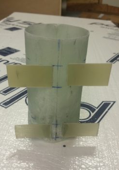
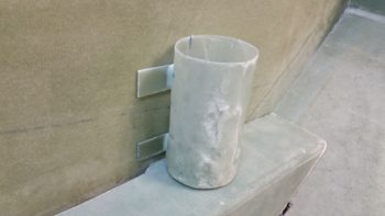
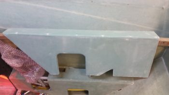
I made up some mounting wings out of some spare glass I had (the same stuff I used for the fuel select valve bracket mounting screw cover) and some G10, and 5-min glued them on each side of the flattest part of the cupholder . . .
I of course did this while it was laying horizontally, like this:
Before doing a final glassing of these mounting wings, I checked out the mounting fit of the cupholder in conjunction with the already test mounted throttle quadrant. Since I dropped down the top mounting wings to clear the top forward throttle quadrant mounting reinforcement spacer, the cupholder looked like to integrate nicely.
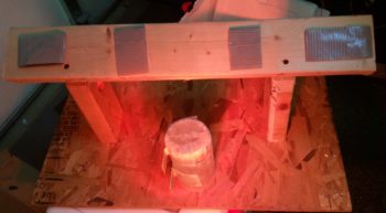
I then whipped up some flocro, filled in the corner gaps between the cupholder body and the wings and glassed them with a ply of UNI and a top ply of BID. I also laid up 1 small piece of BID to cover the last remaining inch-long gap on the bottom corner of the cup holder. I peel plied all the layups and stuck the winged cupholder under the heat lamp.
BTW, that wood frame that the cupholder is surrounded by is the glassing stand I made for the left armrest.
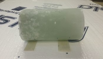
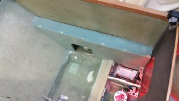
Since I have so many pics in this post, I’m not covering my tasks chronologically, to keep from bouncing around topics with every new pic. Thus, a few hours later, here was the result of my glassing on the cupholder. I know it needs some cleaning up, a result of course of my initial screwup on not taping up the form! Ahh, unintended consequences. But although being ever so slightly heavier, and much uglier, it will still do the job… and of course, except of the top opening, will be hidden away out of site like Quasimodo.
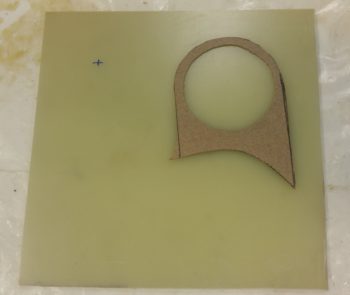
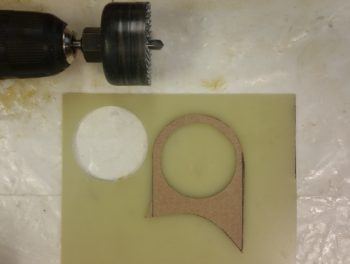
In the real world, while the glassed cupholder wings were curing, I grabbed my last little bit of 1/16″ thick G10 stock and got to work making a mount for the fuel vapor sensor. I started off by making a cardboard template, then once I dialed that in, I transferred it to the G10. In doing so I discovered that the mounting hole for the fuel vapor sensor is not 2-1/4″, nor 2″, but rather 2.034″ . . . some sanding required.
A quick discussion on the requirement for a fuel vapor sensor. I got the idea of having a fuel vapor sensor, something that a lot of boaters have in their engine compartments, from some RV builders. I had pulled it from the install line up, but with the GIB thigh support fuel sumps and a few fuel lines & connections in the cockpit, I decided since I had it on hand it was the prudent thing to do –at least initially– to install it. I do realize that the grams start adding up into pounds, but this is really a lightweight, plastic housed instrument that it, combined with the wiring and aft-mounted sensor, weighs less than 4 oz.
I started by drilling a 2″ hole into the G10 plate.
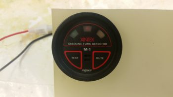
After a few rounds of sanding I got the Fuel vapor sensor control head to slide into place.
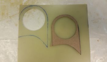
Using my cardboard template I then finalized the shape of the mounting bracket.
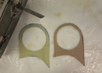
I then used my trusty jig saw to cut out the fuel vapor sensor mounting bracket.
A quick test fit to confirm that the mount’s bottom profile was good.
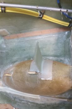
And then, after sanding and cleaning the mounting site atop NB, I 5-min glued the fuel vapor bracket into place.
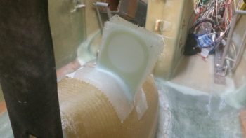
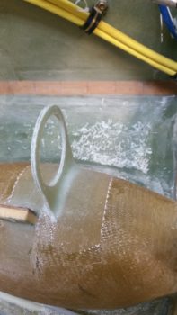
I then prepregged 2 plies of BID for the aft side, and 2 plies of BID sandwiching 1 ply of UNI for the front side. I wet out the prepregged glass and laid it up on each side of the fuel vapor bracket. I then peel plied the base of these layups.
Another look at the glassed fuel vapor sensor bracket.
While the fuel vapor sensor mounting bracket cured (under an added heat lamp as you can see in the pics below), I got to work finalizing the edge cleanup on the left armrest layup.
I then did a minor sanding on the front & aft outboard edge to get the left armrest to fit in place initially. Although I still have a fair number of holes to punch into this thing, I have to tell you it was a great feeling knowing that my last armrest was glassed and that a task that I started over 5 years ago is finally complete!
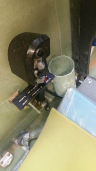
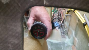
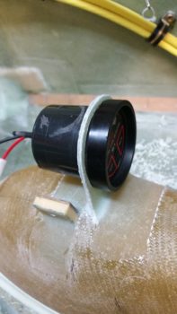
After messing around with the left armrest for a while, I checked the layups on the fuel vapor sensor bracket. The glass was barely pliable — I had let it go just a tad too long– so the razor trimming was a bit more of a workout than if I had caught it about 30 minutes earlier. Still, I got it rough trimmed to the point I could get the fuel vapor sensor control head installed.
To be honest, it felt as if I had mounted the fuel vapor sensor out from centerline a bit more than where I had originally set it in place.
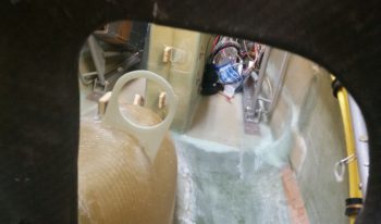
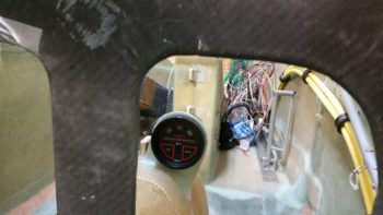
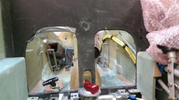
I grabbed another shot looking straight ahead and it still seemed to be peeking out from the center panel strut just a tad more than it had in my original mockup. Hmmm?
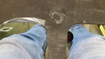
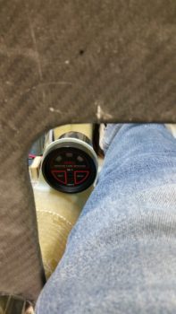
I finally decided that I couldn’t go to sleep tonight if I didn’t know exactly what the clearance would be between the fuel vapor sensor and my right leg . . . so I assembled all the dismantled pilot seat area stuff to allow me to climb in and check it out. I have to say that it really presented no obstruction or clearance issues at all. It IS CLOSE, but to touch it I have to force my knee unnaturally inward. I still would have mounted it about 1/8″ to 3/16″ further inboard if I had a redo, but that’s more of a mental thing than it is a physical clearance issue. Thus, this thing is pretty much in plain sight during my visual scan, being that I installed it about as far off CL as possible without having any leg clearance issues.
I may still sand down the outboard edge of the mounting bracket a hair just to keep it more in line with the instrument face, to keep any errant scrapes from happening during warm-weather flying in shorts.
This pic might provide a better visual as to the clearance I have between my leg and the fuel vapor sensor. I’ll repeat that I had ZERO clearance issues, and that to actually touch the sensor to the point I really felt it, required in inward press on my knee that was not at all comfortable position-wise, and not from the pressure of the instrument mount.
Tomorrow I’ll continue to work on all this pilot area stuff, including populating the left sidewall with components. . . and getting the left armrest cut and shaped to both fit into its place on the left sidewall, but also to accept the throttle quadrant, cupholder, etc.

