
On 3 sides: front, left and right…
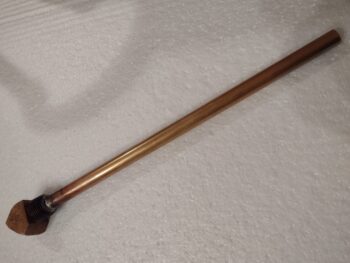
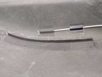
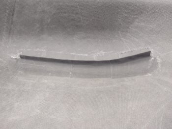
But first, I started out today wanting to get a task knocked out that his been literally staring me in the face (sitting on my coffee table!) for a couple of months: the brazing of a 1/2″ brass tube into the brass 1/2-NPT 45° street elbow that will be my new oil heat oil sump fitting with standpipe to replace the massive 90° steel standpipe that is jamming up my SCEET tube underneath the engine.
A couple of months ago I had called literally about a dozen welders to see who could braze brass stuff… well, of course I started locally and moved out geographically. The welder that I went to today is about 45 minutes from my house, so I figured I would go for a little drive this morning and get this thing done. The good news is that they did it while I waited, after a discussion of exactly what my requirements were. I wanted it brazed because A) I don’t have the Oxy-Acetylene torch kit to do it, and B) I’ve never done it before (if I had A than I would forge ahead and disregard B).
I told them exactly what it was for since their initial guess was that it was for fuel… fuel of course typically being cool. Nope, this is for oil gents and it’s an oil fitting with standpipe inside an oil pan feeding an oil heat exchanger via a pump. Of course the only thing I was purposefully vague on was that it was going into an airplane… any homebuilder knows how that conversation can turn out.
Well, they came out of the shop and asked me if the length was critical because they blew out the sidewall of the tube (I guess I’m not the only one who does stuff like that!). I said no, I had plenty there. They told me that the brazing rod they had was too big, and they had to find some smaller stuff. Then the boss handed over my project to one of the minions, who peppered me with questions so we went over the specs and requirements again. I was out front BS’ing with the owner and another customer… when, after over half an hour later out comes my pipe and street elbow joined as I had wanted. However, it didn’t look like it was brazed, but rather soldered. Hmmm? I asked him if it was brazed or soldered, and he said it was a high temp solder since they didn’t have (or couldn’t locate) any smaller diameter brazing rod. I responded that I was highly skeptical since I hadn’t heard of that, and he assured me it would meet my requirements… I thought maybe I had learned something new, but spoiler alert: it doesn’t meet my requirements.
When I got home I heated up my stove to 400° F and put the fitting/standpipe in there for almost an hour. I pulled the combo out with oven mitts and could easily pull the joint apart. Now, while it was baking I did some research on how hot it gets inside a Lycoming engine. I couldn’t find any actual data on that, but Lycoming does state that the oil temp isn’t supposed to get over around 235° F, but I want my components to be able to withstand at least 350° F, with a safety margin… thus the 400º F. I don’t know if I’m being too stringent, but I know that a brazed part and definitely a welded part would have no issues with my required temp tolerances.
So, alas, I will have to do this myself!
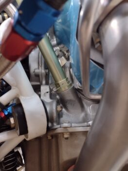
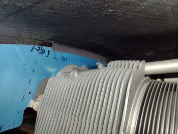
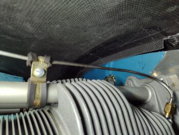
My first task out in the shop was to rewire the oil level tube to ensure it stays nice and snug in its place…
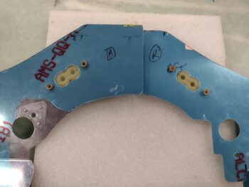
I then marked the top cowl rib baffles at just over 1/2″ high on the peel ply, which gave me some contrast to see my cut line. Here’s the left side.
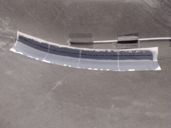
I then trimmed the rib baffles with my Fein saw. Again, here’s the left side.
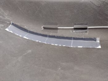
I also trimmed off each end, forward and aft, of the rib baffle on both the left and right sides. I then cleaned up the cut edges with a sanding block to finish them off. And here are my rib baffles, which I now consider merely an adjunct to my baffle setup. As I told Mike Beasley, I’m pioneering a new “Hybrid Baffling System” … ha!
I then did a trial fit of the top cowling to see if I had any clearance issues with the rib baffles while setting the cowling into place, which I didn’t. I then looked up inside to see how the rib baffles were positioned in relation to the actual baffles, and all looked good. Again, I do have that minor kick-out inboard for the last aft few inches on the right side, but besides that they looked really good.
I then marked, removed, and did a final trim on all the baffle segments to dial in about a 1/2″ gap between baffle wall and inside top cowling all the way around. The only segment that did not need trimming was the aft right baffle around cylinder #2.
Although I had a lot more on my to-do list to get done today than I actually did, one such task was to get the top spark plug wire baffle seals configured on the front baffle wall segments. I made up a cardboard template and then assessed different access points for the Electroair spark plug wires to traverse the front baffle walls.
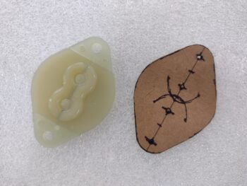
As you can see, I decided to put them equidistant from the engine centerline and cant them at an angle. After marking up their respective locations I drilled the outer AN3-sized holes for each seal, then used a 3/4″ hole saw to drill the center “figure eight” holes. I will note that these seals are for mags which have 5mm diameter spark plug wires, whereas my Electroair spark plug wires are 8mm in diameter… yep, nothing standard and even another required mod in drilling these suckers out!
Tomorrow really will be centered more on the bottom cowl intake ramps, which I’ll work over the next few days as I then will roll into working the exhaust pipes… and start prepping to do some major sanding and micro fill on this bird. At this point I can’t really do a whole lot more with the baffles since I need the CF inner baffles in place to do the final positioning of at least the front baffle segments (I’ll construct the aft shelf and skirt around the inner baffles), and I’m still waiting to receive the form set for the inner baffles.