
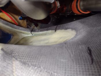
I started out today sanding the razor trimmed edges of the top aft center 1-ply CF layup on the bottom cowling. I used flox in spots around the edges (as well as micro) in “flox” corners I made around the perimeter of the foam to secure the ply of CF. Some of that flox and micro squeezed out and that is the light stuff around the edge of the end piece… it’s smooth to the touch but looks like the corner edge has small divots in it. But it doesn’t.
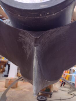
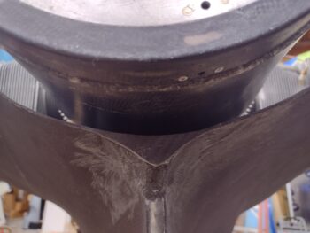
Here’s another shot. Obviously I put the spinner flow guide in place to take these shots to see the relationship and clearance between the two.
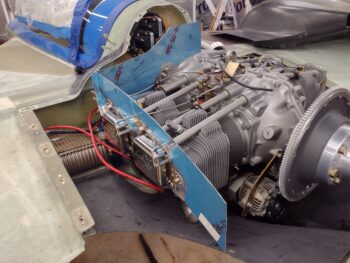
I then got busy back on the left side baffles. I did a number of iterations, tweaks, additions and trimming of the tape and cardboard templates, replete with iterations of top cowling on and off, to dial in the height of these left-side baffles.
After a good bit of tweaking, and satisfied with the heights for the left side baffles, I took off first the side baffle templates and marked up the actual VAN’s baffle segments for trimming. I will note that to get the side baffle segments into place I had to do some judicious trimming and filing (interestingly) on the interfacing edges of the top doubler plates… maybe 0.050″ to allow the baffles to seat properly and the mounting screw holes to align.
After marking both left side and front baffle segments for trimming I dove in with my Dremel tool and trimmed ’em down. I then remounted the actual left-side baffles in place.
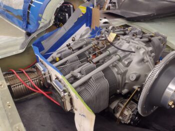
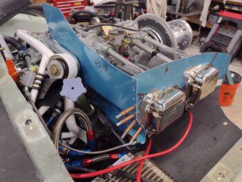
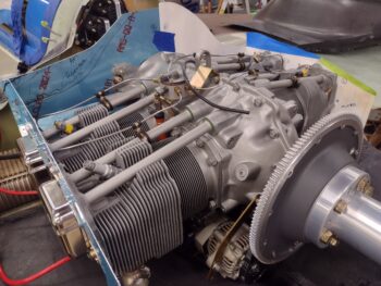
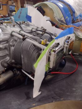
Here we have the initially trimmed left side baffles in place… note all the securing mounting screws are installed.
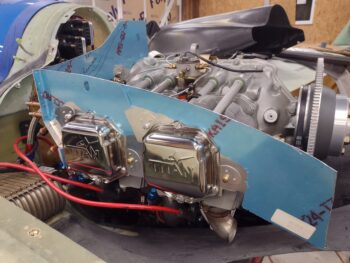
An inside shot of the baffles. Clearly, most likely the center baffle area height is just a hair low on these VAN’s baffles, so I may be adding more on the top center edge. I’ll of course wait until I have the exact height dialed in for the front left and right baffle segments.
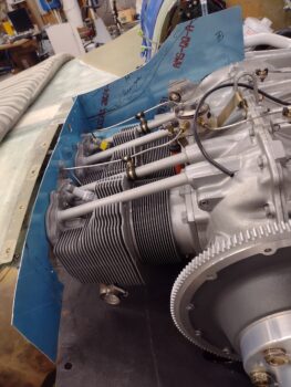
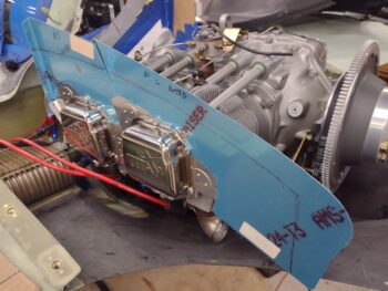
Here is the front left corner of the left-side trimmed baffles. The fact that the corner aligns between front and side baffles is great to see, as denoted by the Clecos securing the adjoining rivet holes with just a minor alignment in the top hole using a scribe.
Besides the rivets at the corner and the mid-engine angled bracket that secures the forward baffle segment in place, there are 3 screw positions as well: 1) near the engine mount bolt (that I drilled out & tapped), 2) at the forward bottom side of cylinder #3 (behind the second from bottom Cleco) and 3) the bracket arm (behind the oil dipstick tube), that I attached with rivets.
The first two screws went into place nice and EZ, but this latter bracket screw point needs some fine trimming (no pic) to allow it to sit flush with the engine side and for me to get a screw into the mounting hole.
I then spent a couple of hours assessing and working the armpit intake ramps. My initial task was to take the template that Mike Melvill included with the cowlings that is used to configure and construct the inboard wall of the intake scoop. Mike M. had a traditional oil sump and intake tubes on his IO-360, so his setup sat a bit higher up than my cold air induction tubes.
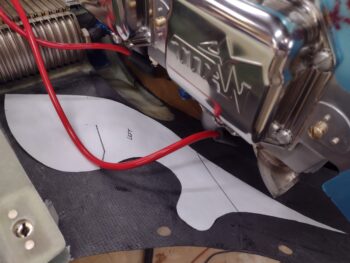
I used regular cardboard to construct my inboard intake wall template since clearly I couldn’t just use Mike M’s template as plug-n-play. After a half-dozen iterations of trimming and cutting, I finally got a decent initial fit.
But then I ran into another issue. You see, on the corners of the inlet ramp (baffle) templates there is an annotated measurement. A note on the armpit inlet template page states that those measurements are from the forward cowl trim line. However, on a diagram in the cowling install instructions it shows these measurements as taken from the front face of the armpit inlet.
I remembered the note on the template page, but pictured the diagram from the instructions (I’m a visual learner/rememberer). I spent a good 45 minutes chasing my tail because these measurements, and the fit of the ramps compared to the inboard wall (it has the ramp positions marked on the template), just wasn’t jiving. Finally I went and got the install instructions from the house and realized that the measurements listed are different… obviously since the starting reference points are different.
Mystery solved! You can see the aft ramp line on the wall aligns with the proper marking [you still see the faint remains of the previous mark about an inch forward (left in pic) that I removed with Acetone]. That being said, required tweaks still remain left to do to get the inboard wall dialed in to fit. Note specifically that the inboard wall front nose/tip is not intersecting the front corner edge of the bottom cowling in the correct spot.
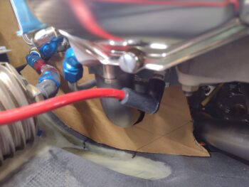
Here are 3 of the 4 hash marks I made with the CORRECT measurements for the left armpit ramp positions.
It was starting to get late in the evening, and I was mentally spent from the cluster that was my initial outing on the bottom cowl cooling ramps and walls.
Since my right side baffle templates were destroyed during Hurricane Dorian (and the spinoff tornado that hit my hangar) I went ahead and taped the left side baffle templates in place on the right side, since I’m really only looking to dial in the heights at this point.
Clearly I put the front right baffle wall template into place as well. Again, these thick paper templates are from Mike’s “Beasley Baffles.”
I’ll be attending a concert tomorrow night with Jess, so I suspect I won’t get a ton done on the build. But I would like to get the initial trim of the right side baffles knocked out and both left and right side baffle heights dialed in enough to allow me to mount the top cowling. Whatever time I have left I will also press forward with the bottom cowl cooling ramps and walls as well.