
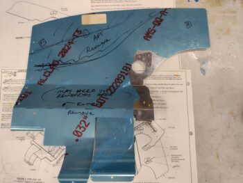
Since my top cowling has an increased internal height towards the front end vs the Task cowlings that Mike Beasley has and based his “Beasley Baffles” on, the front wall of my baffles will need to be 2-3″ higher than both Mike’s and what I initially marked onto my VAN’s baffles using his as a template.
The reason this is significant other than just trimming the baffle walls to the correct height, is that just above cylinder #3 & #4 on those baffle segments there are reinforcement stiffeners that cover, in part, an access hole to get a ratchet wrench extension through to remove/install spark plugs (pretty cool actually). If I leave those reinforcement stiffeners off then I will have to contend with a row of unused rivet holes. Cleary this wouldn’t even need to be considered if the baffles sides were significantly shorter (ok, maybe 1-2 holes top… covered by the baffle seal material).
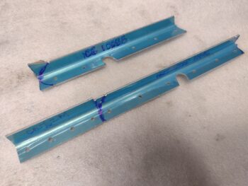
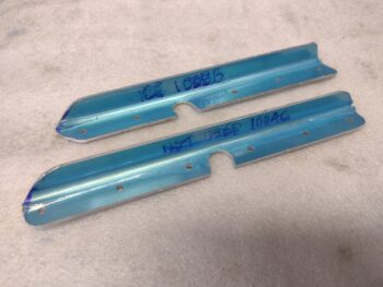
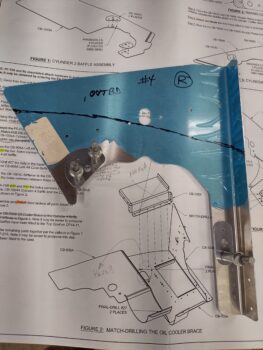
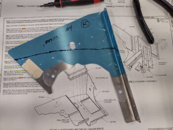
In short, I needed to create those stiffeners out of the extrusions provided (pic #1). Here is my effort in doing just that (pic #2).
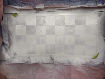
I then spent a good 15 minutes playing ‘musical squares’ by pulling the tape off the unpainted squares and covering up the white squares on the interior panel of the aft nose/avionics cover.
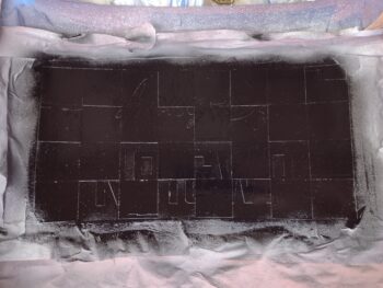
I then took the cover outside and shot a few coats of black paint. This is about an hour later… I’m not overly satisfied with the final look of the black paint, so I’ll wait the requisite 48 hours and hit it with another coat or two.
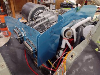
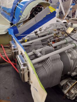
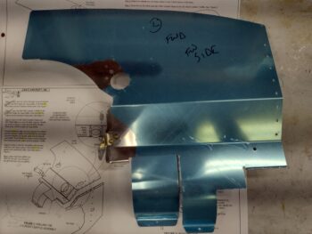
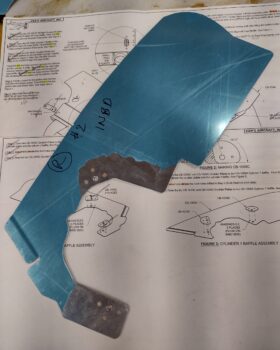
I then test-fitted the 4 baffle panels from the VAN’s kit that make up the front right half and the right side around cylinders #2 and #4.
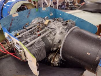
Here’s a shot of the untrimmed right side baffles test-fitted in place.
I grabbed a shot to show that these baffles fit well and even have all the mounting screws installed (pic #1), and the front right corner is looking good as well (pic #2).
Here’s a shot from the front looking aft of the right baffles test-fitted in place.
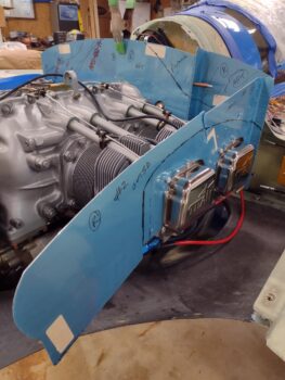
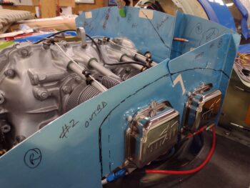
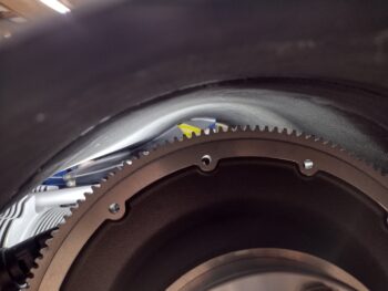
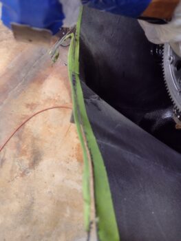
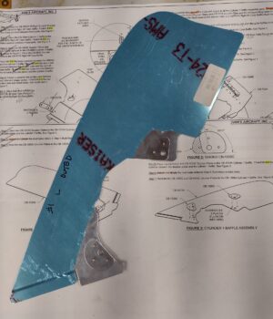
I then took all the VAN’s baffle segments out and put the front left baffle piece in place using the cardboard template from Mike’s “Beasley Baffles.” I extended the top with cardboard secured by tape in what I estimated would be close to interior top cowling profile. For the last inch —mimicking baffle seal— I used gray duct tape.
I then mounted the top cowling back in place. Here’s a shot of the lit up front baffle top edge from the back of the cowling. I took about a half dozen more shots both from the back cowl opening and through the oil check door to give me a decent idea of what the baffle height and shape needs to be for the next round of trimming and checking.
Before I finalize the final configuration of the “smile” and the top aft center of the bottom cowling, I needed to do a no-kidding final trimming of the bottom cowling aft edge. It was a little tricky to do because coming inboard on the top cowling, from the flat “shoulder” sections, it starts to angle aft just a bit.
I marked a loose cut line on the taped up aft edge of the bottom cowling and then trimmed it with the Fein saw. I then used a couple of sanding boards to finish creating the final aft edge of the bottom cowling.
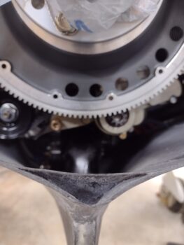
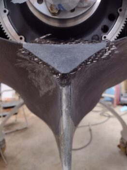
With the bottom cowling aft edge configuration finalized, I could then turn to finishing the top aft center area of the bottom cowling. I must have looked and stared at it for a good 10 minutes trying to figure out what I wanted it to look like. The problem is I had no real design goal of what I wanted it to look like, other than removing the “V” that was there previously and creating a round-shaped lip. Well, I actually did that by glassing in the edge and creating the 3-ply CF “smile.”
After doing some judicious sanding of the curved center area (just above the fin TE) and the sides, I decided that it would take a whole lot of work and more glassing to create something that I didn’t really know what I was creating. I made a command decision and decided this looks good enough and just to cap it with a ply of CF.
There was just one problem…. I had put duct tape covered with peel ply inside the layup to unearth when I trimmed all the “offending” lower lip structure away to reglass it. Now I was getting lazy and just laying up a final ply on the end of this structure, as is.
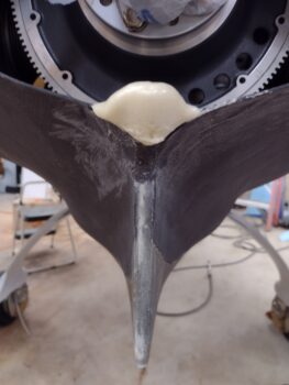
I spent well over half an hour digging out the foam, tape and peel ply before then pouring in a new batch of foam (pic 1). I pondered using dry micro, more CF, but in the end just put more foam back in this dead space (being a rascal, I thought about leaving it open and telling people that it was a “vent” for some secret engine component… ha!)
After the pour foam cured, I then shaped it for some “flox” corners just prior to laying up a singly ply of CF (pic 2).
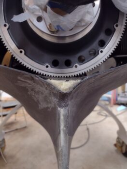
Which I did next, using MGS with fast hardener. I then of course peel plied the layup.
One cool thing about the VAN’s baffle (besides NOT having to cut out all the raw aluminum) is at each mounting screw hole they designed in a reinforcing doubler plate to help protect and secure the thin aluminum baffle panel. The downside to this cool feature is that you, the builder, have to rivet all these doubler plates into place… after deburring and countersinking (or dimpling) the inside of the rivet holes.
As you can see, here are the 2 doublers for the cylinder #4 baffle segment, Clecoed in place for final rivet hole drillouts with a #40 drill bit.
And here is the cylinder #4 baffle segment with the doublers riveted in place.
Following the VAN’s baffle install manual, the next section up was the front left baffle wall. This segment got one triangular doubler and one mounting bracket riveted onto it.
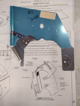
Then the doubler-adding for the left side Cylinder #3 baffle segment.
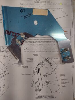
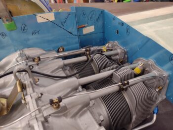
And finally, the aft side cylinders baffle segments’ doublers. Here is the right side cylinder #2 baffle segment doublers.
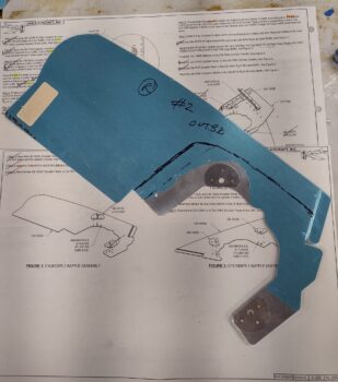
I figured I would include a shot of the interior side of these baffle doubler plates riveted into place… here is the same cylinder #2 baffle segment with the doublers riveted into place.
And finally, the cylinder #1 baffle segment with the doubler plates riveted into place. This is the one odd duck since the forward doubler plate has to be trimmed by about a third to fit into place and only gets 2 (vs 3) rivets.
All told, riveting on the baffle doubler plates took over 2.5 hours.
After taking a break and cleaning up a bit, the aft ply CF layup on the bottom cowl was cured well enough to get razor trimmed. And even cured enough for the peel ply to pull off without any issues.
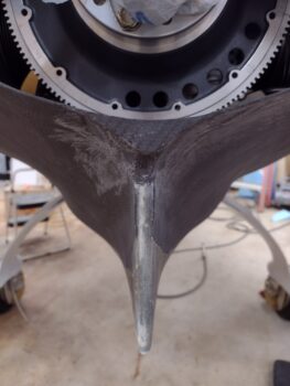
So here is the new look of my center aft top of the bottom cowling. I kind of like the blunted look and again, couldn’t think of anything better that didn’t involve a ton of work… so I’m leaving it like this and moving on to get this plane in the air! Tomorrow I’ll be starting the internal baffles and ramp installs for the lower cowling. I’m sure I’ll be doing some more baffle work as well.