
I started off today pulling the peel ply from the 5-ply flanges I just laid up for the required mod for the new Melvill CF cowlings.
I’ll reiterate that I’m essentially copying how Mike Melvill installed his new style CF cowlings, first by creating the original stock plans cowling lips, then modifying them to convert them into exposed flanges verses lips that simple secured the front edges of the cowlings, only on the inside of the lips. The wing interfaces and configurations are essentially the same.
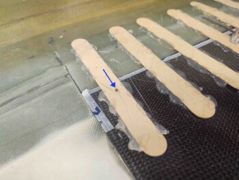
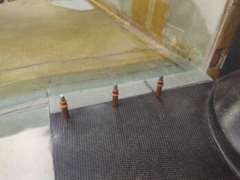
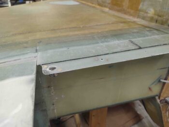
Then, before I popped off the hot-glued popsicle sticks, I determined where my front outboard corner CAMLOC would be located and drilled a 1/8″ pilot hole. Admittedly I would have preferred it a hair more outboard —by maybe a 1/4-3/8″— but when I laid up the glass on the strake & CS spar for this new flange I errantly went off the firewall side first rather than starting at the wing side. With a healthy flox fillet created along the junction, I didn’t want to mess all that up by pulling and relocating the glass outboard…. so it is what it is.
Here’s the 1/8″ pilot hole coming through the top corner popsicle stick.
I then installed a cleco in the corner and started removing the hot glued popsicle sticks.
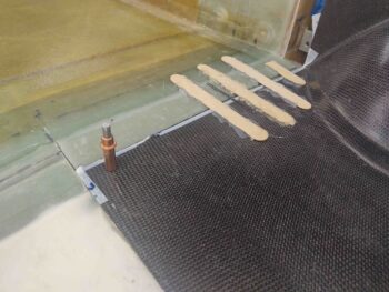
I eventually got all the hot glued sticks removed from both sides. The reason I didn’t drill a pilot hole on the right side (as situated) is that inboard corner needed to come outboard by about 1/16″ (or so I initially thought… see below).
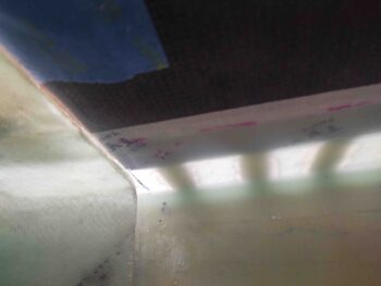
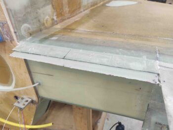
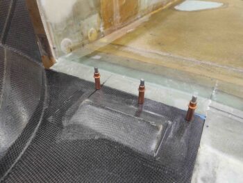
When I removed the bottom cowling to trim the left cowl edge about 1/16″, I then checked out my freshly glassed flanges. Here we have them with the top peel ply still on.
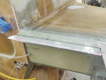
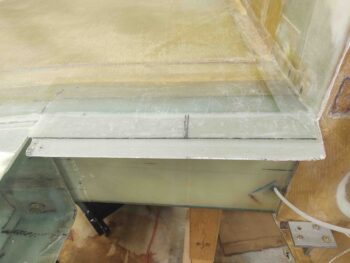
I then promptly ripped off the peel ply . . .
And then trimmed up the edges. I’ll note that I was shooting for a 1.2″ wide flange on each side, but because of mental math deficiencies in calculating the required width of my glass, I ended up with barely an inch on each side… workable, but not optimal.
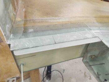
After resetting the bottom cowling back in place, I then checked the corner alignment again on the left side (right as situated inverted). My 1/16″ wasn’t enough and I still needed at least another approximate 1/16″ trimmed off to bring that corner outboard in line with the corner of the strake/fuselage intersection. My closest guestimate is that I shaved about 5/32″ total off the outboard edge of the cowling to get this inboard corner aligned.
I’ll note here, since I don’t show it in the pics, that I’m not trimming the entire edge of the outboard cowling side, but rather just the front 6-8″… enough to allow the front edge of the cowling to sit flat against its mounting flange. I did this on both sides, to be clear.
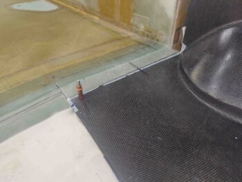
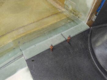
Thus, once the outboard corner was good, based on the alignment of the inboard corner, I then drilled a 1/8″ pilot hole and secured the left side cowl front corner with a cleco.
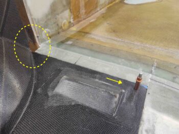
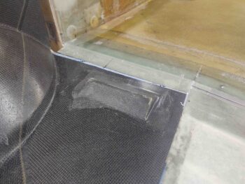
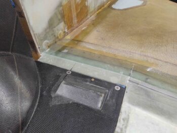
The thick black line you can see in the pic below and in many of the previous pics is the outboard edge of the armpit intake scoop that I had previously quickly mocked up with a 3/4″ foam spacer with the sidewall to find this edge. Since there is also a required 3/4″ gap between strake bottom and intake scoop —which provides a hair more clearance for a slightly angled screwdriver— I skooched the inboard CAMLOC in a bit so it is basically centered on this line.
With my inboard and outboard front cowl horizontal edge hardpoints located, I then simply split the difference (3.3″ each side) for the middle hardpoint.
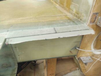
I then drilled out the outboard corner pilot holes to install a CAMLOC.
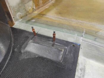
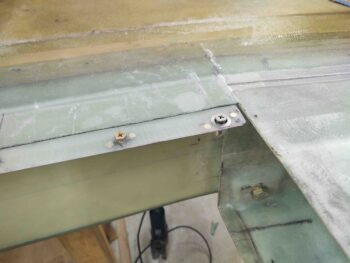
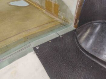
Here we have the CAMLOC receptacles mounted on the flange in the front outboard corner for the bottom cowling.
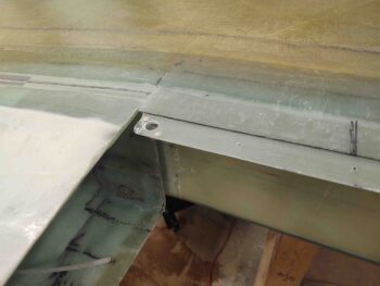
I’ll digress a bit for a brief philosophical building preference discussion. I know some builders prefer to cleco everything up before then installing the hardware. Personally, after experience with the aft nose/avionics cover, I like to actually get the hardware installed one point at a time (here, both sides concurrently) since there are minute shifts that happen when installing the hardware, and I want to catch/gauge/note those as they occur and adjust accordingly.
Moreover, on the front edge of the cowlings I’ll be using primarily fixed CAMLOC/Skybolt receptacles, whereas on the wing junctions I’ll be using all floating receptacles. Since I failed in taking any hardware pics of the inside of the flange, I’ll note that I am installing the Skybolt lightweight stainless steel fixed receptacles here.
After ensuring my bottom cowling alignment was good, especially that it was still centered on the aircraft centerline (it was) I pressed forward with the next hardware install… moving inboard.
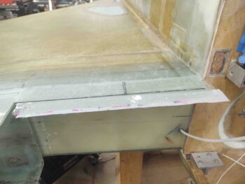
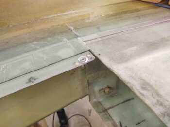
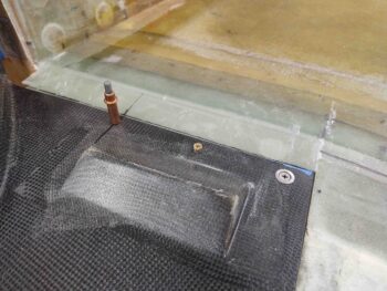
Again, I know that I quite often do things differently than other builders, but at this mid hardpoint location I’m installing a K1000-3 nutplate. I’m doing this at a point close to the center of each forward cowl lip on the advice of Wayne Blackler, who noted that the combined internal engine compartment pressure and external on-rushing air pressure can be enough to overwhelm a CAMLOC and pop it free, or worse out.
To secure the front cowl lip in order to avoid this —especially since one of the big changes Mike Melvill made was to have the front cowl lip rest ON, not under, the strake/fuselage cowling flange— I am simply installing one screw on each front cowl lip, both top and bottom. Obviously this means to remove both top and bottom cowlings I’ll have to contend with a total of 4 screws. Not bad at all for a little bit of insurance in my book.
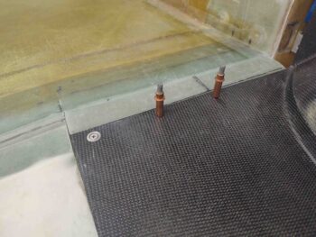
Again, I then double-checked the fit of the bottom cowling with the screws installed.
I’d be remiss if I didn’t note that the screws I have installed here are NOT the ones that will be installed on the flying airplane… much like the clecos will not be left in place either! These screws have a hex head and can be either driven by a phillips screwdriver, a hex head screwdriver, or a socket. I’m not going to mess around with driving countersunk screws in and out repeatedly during the building process when I can TEMPORARILY use these screws/bolts instead. They are simply way easier to use. I know this is a difficult thing for all you OCD types that have to look at this egregiousness, but I’m not going to suffer through a major building PITA to appease the sensitivities of builders/viewers who can’t grasp this concept! There, rant over.
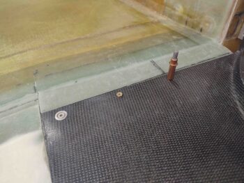
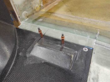
I then moved inboard to the last hardpoint on the bottom cowling’s front horizontal strake-mounted interface to install yet another CAMLOC each side.
The bottom cowling centerline is still just about dead even with the aircraft centerline, so everything is still tracking good at this point.
Tomorrow I’ll start work on the lower center bottom cowling install by first glassing the original 1.6″ lip off the aft fuselage and around the firewall to intersect with the bottom cowling’s front edge. After that I’ll then add the modified flange to allow the “U” section of the bottom cowl to be secured to the fuselage/firewall.