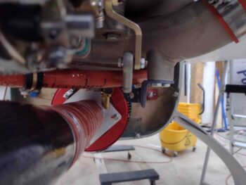
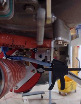
Today was all about some final dimensional tweaks before diving into machining the throttle cable mounting tab and the throttle cable bracket.
Before I machined either the small throttle cable mounting tab or the throttle cable bracket that it attaches to the side of, I needed to determine the attachment configuration and geometry of the throttle cable to the fuel injection servo throttle lever arm. The big question was how I was going to mount the rod end: on the inside or outside? Moreover, would it work in either position?
Looking at the rod end geometry was all of course in direct relation to both the throttle cable mounting tab (minor corrections) and the throttle cable bracket itself (major corrections).
I found that unless I wanted to change the design of the throttle cable bracket, that I would definitely need to move the throttle cable inboard just a hair to better align with the inboard mounted lever rod end… 0.2″ is what I decided on.
So I modified the throttle cable mounting tab in CAD and 3D printed a new mockup of it with the throttle cable mounting hole moved inboard that 0.2″
However, when I mounted the throttle cable mounting tab to the throttle cable bracket, I found that I overshot by a good little bit. At least 0.05″. I decided to back off to having the hole on the tab only moved inboard simply 1/8″. To be clear, I’m optimizing here (some call it being anal or OCD… ha!) although there is a good bit of inherent wiggle room with the designed pivot of both rod end and cable end, so cumulatively between the two I should have decent leeway in my configuration.
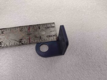
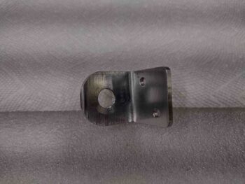
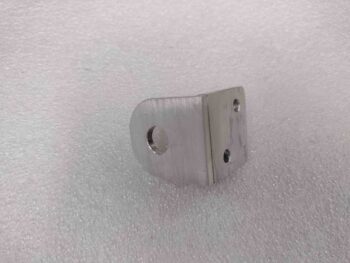
I didn’t 3D print another throttle cable mounting tab, but rather just simply declared my 1/8″ inboard hole move a success and proceeded to machine the tab out of 1/8″ thick 2024 aluminum. Here is the throttle cable bracket mounting side (2x 3/16″ screw holes).
And here is the throttle cable mounting thru-hole, which is 0.45″ diameter. Notice I left a considerably larger amount of “meat on the bones” surrounding the mounting hole on this version as compared to my previous 3D printed mockups.
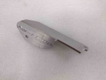
Here we have a couple shots of the machined 2024 aluminum throttle cable mounting tab.
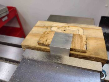
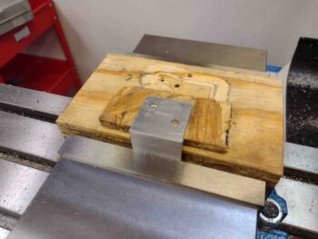
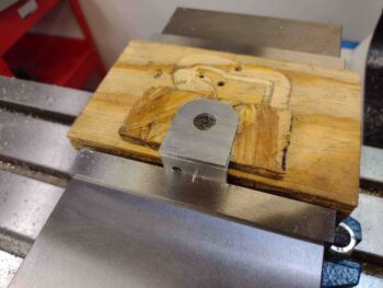
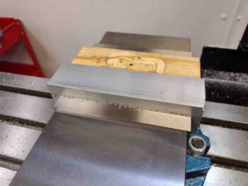
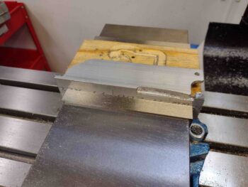
I then cut my foot-long piece of 7075 angled aluminum in half and mounted one of the 6″ lengths into the milling machine’s massive vise. Pic #2 shows the lower, vertical side of the throttle cable bracket after I finished machining that side. Note the last minute addition of a tab and 3/16″ hole at the very front lower edge of this bracket… I’ll show what that’s for below.
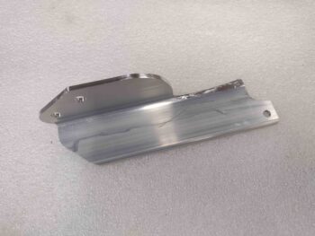
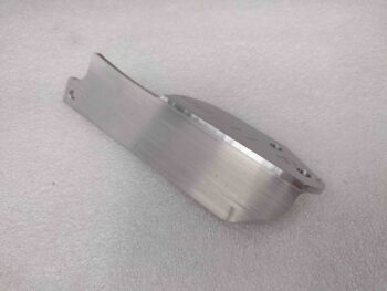
And here is the machined 7075 aluminum throttle cable bracket after I did some initial cleanup on some of the harder to machine areas.
And a couple more shots of the just-machined 7075 aluminum throttle cable bracket. I used 7075 aluminum since it’s significantly stronger than 2024 (over 30%) and weighs virtually the same. I wanted to go with the strongest strength aluminum I could feasibly acquire —without having to use much heavier steel— since there is a good bit of cantilevered forces going on between the respective plenum boss and throttle cable attach points.
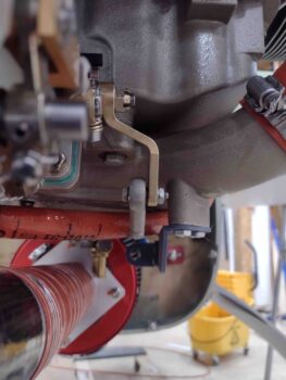
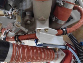
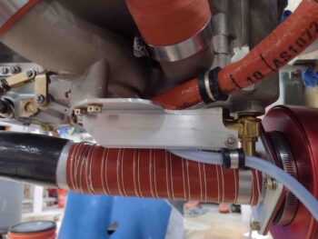
Here we have the hot-off-the-press throttle cable bracket test mounted into position. Note the forward tab is where I conveniently hitch-hiked a ride for an Adel clamp to secure the Sniffle Valve drain tube…. shameless!
And another couple shots of the test mounted throttle cable bracket with both Sniffle Valve tube Adel clamp installed and the throttle cable mounting tab clamped into place.
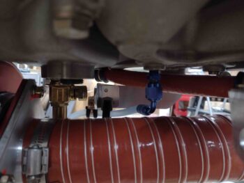
Another “alignment” shot much like what I started this blog out with showing the general relationship between the servo throttle lever rod end and the throttle cable mounting tab. I think this dog should easily hunt, but if not, it won’t take long to gin up another throttle cable mounting tab on the mill.
And with that folks, I called it a night. Tomorrow I plan on re-machining the mixture cable bracket in 3/16″ 6061 aluminum to hopefully be done with making brackets for these cables.

