
With the firewall floxed wood plug & glass cured, I started off this morning by drilling out the throttle cable 5/16″ test/pilot hole to 5/8″ to allow me to install the blue aluminum throttle cable pass-thru.
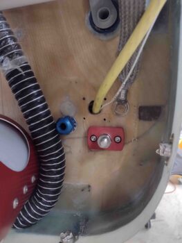
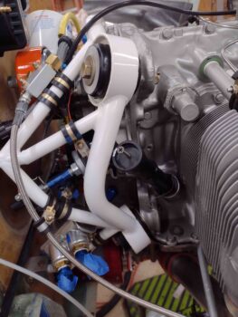
Here’s a wider angle shot of the just-installed blue aluminum throttle cable pass-thru.
Here’s another angle showing both the mixture and throttle cables blue aluminum pass-thrus.
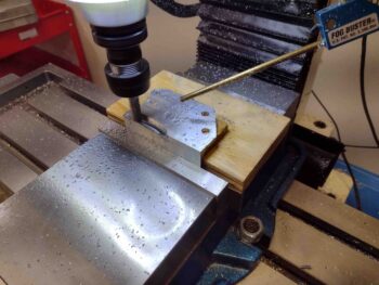
I then turned my sights on machining my scrap piece of 1/8″ thick 6061 aluminum to create the mixture cable bracket. Serendipitously, this piece of aluminum was exactly the correct width.

I worked up the machining code (“CAM post-process”) in Fusion 360 and loaded it into the milling machine’s CNC control program (Acorn).
I started by drilling the holes while there was still more material on the part.
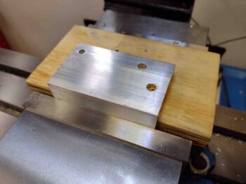
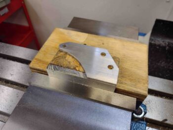
And then machined the remainder of that side.
Voila! The first half of the mixture cable bracket.
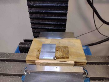
I manually trimmed off the excess on the bottom side of the bracket, where the cable mount tab is, to reduce the machining time and chip mess.
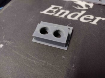
Here we have the newly machined mixture cable bracket along with its 3D printed mockup.
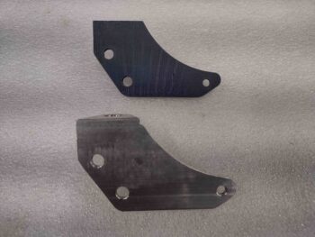
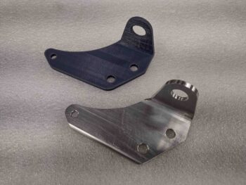
I honestly think this 1/8″ thick mount would work fine, but after assessing it I prefer the actual cable mount tab to have a bit more material around the hole. I will most likely remake this bracket in 3/16″ 6061 when that stock arrives.
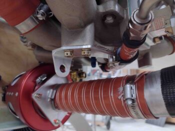
I then test fit the new bracket… it fit like a champ.
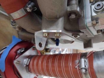
And then test installed the -6 fuel hose Adel clamp. I want it just a hair lower, which is easily done with an extra thick washer on install (or the added 1/16th of inch with a 3/16″ thick bracket), but the Adel clamp’s fit was spot on as well.
I did leave out a very important data point while making all the measurements for my throttle and mixture cables: I forgot to account for the length of the HEIM rod ends on each end of the cable. I know, silly mistake.
To be clear, I didn’t forget them in reducing the overall cable length with the HEIM (or fork) rod ends in place, but I didn’t take the HEIM rod ends into account on the distance between servo throttle/mixture lever arm hole and cable mounting on the bracket. In the Push-Pull documentation it shows that distance as 7.38″ with a 3″ cable travel… and I was so focused on figuring out the cable travel that I didn’t add in the extra 0.5-0.6″ that the HEIM rod end will protrude beyond the cable rod when everything is mounted up. Not a big deal, especially since I caught it before machining the throttle cable bracket… and the 3″ travel gives me some wiggle room since it is a bit more than the overall travel of the servo mixture and throttle levers.
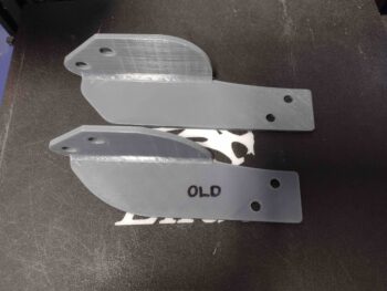
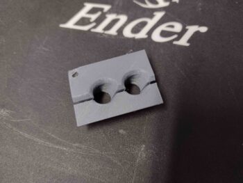
Ok, all that bantering to state that I added a half inch to the length of the throttle cable bracket and 3D printed a new mockup bracket. Also, you may note that I put a bit more “meat back on the bones” by trimming less original material off the top aft and front sides of the bracket.
I also 3D printed the final install version of the GIB seatback cable pass-thru, with a 100% fill so it’s now a solid little chunk of plastic.
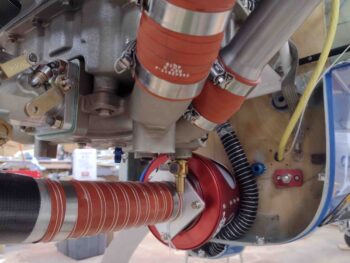
Another small but significant task on my list was to do a final mount of the SCEET tubing on the front end of the air induction tube. There was actually about a 1/4″ less in length on the SCEET tube than I was aiming for, so it was a little closer to the front edge than I was wanting… but with my Clamptite tool I secured the SCEET tube in place tightly with safety wire onto the front of the air induction tube.

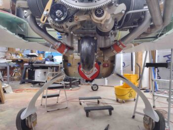
My next task before the engine comes off (btw, obviously I went off onto a throttle and mixture cable rabbit hole to get those ordered before the engine comes off for a bit of time) was to evaluate the oil dipstick/filler tube. Mine sits with the top of the filler neck right at the major engine mount tube so closely that I can’t even get the dipstick threaded into place.
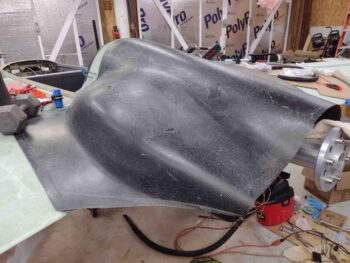
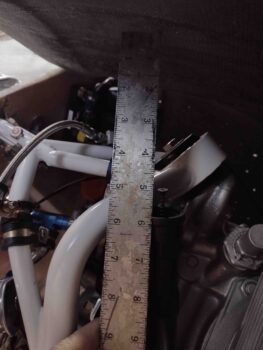
I wanted a good idea of how to fix this oil dipstick issue, but I needed a no-kidding assessment of how it fits inside the top cowling to press forward. So I set the top cowling in place and weighed down the corners so it was reasonably close to how it will sit after final install.
I then climbed underneath and measured the distance between the top of the oil dipstick tube and the cowling. With the cowling still sitting about a 1/2″ off the CS spar, I’ll call this a good 5″ of clearance. Clearly I don’t want to have to reach that far down into the cowling to check my oil, so a new oil dipstick tube will be on the to-do list of required items. I’ll visit my local A&P at the airport and see if I can swap this shorter dipstick tube for a longer one.
And with that, I called it a night. I will be most likely machining up both the throttle and mixture cable mounting brackets before I pull the engine off the firewall. So still at least another 2-3 days before the engine comes off.
It takes a strong builder to admit his dipstick tube is too short 😂
Haha… yep!