
After a bit of research last night and this morning, I started off this morning by finally getting around to gathering up my GRT bayonet CHT probes threaded adapters for install.
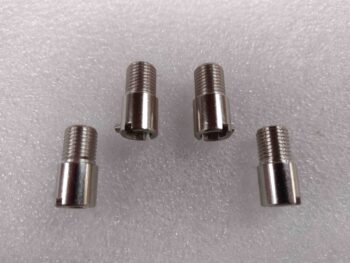
I figured with these things getting mounted into hot cylinder ports that I might need some type of gooping substance, and I was right: anti-seize. So I added a bit of anti-seize to the threads of each CHT adapter and installed them on all 4 cylinders.
I then played around with the actual bayonet CHT probes to find a good depth from probe tip to attaching collar that offered good spring pressure to both press the probe tip against the cylinder wall and also keep the probe securely in place. I got 2.5″ from the end to collar. I may increase that just a hair on final install, but that measurement seemed just fine.
One thing I didn’t expect was that the leads on the actual CHT probes would be so darn long! On the right side I’m barely going to have any length of the red & white CHT wire pairs coming out of the P10 connector. Close to the same on cylinder #3 on the left side as well.
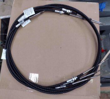
I then found a surprise on my doorstep since I never got any shipping notification: my throttle and mixture cables from Push-Pull cables! Here’s the initial unboxing:
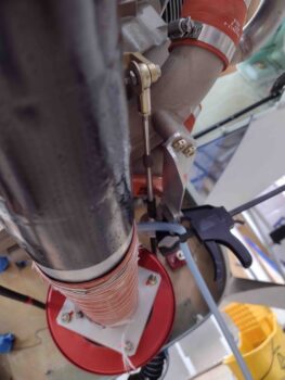
I then spent the next few hours working the throttle and mixture cable installs. Here we the mixture cable installed from the pilot throttle quadrant, through both seat bulkheads, then the cable bracket via the firewall pass-thru, and finally to the fuel servo mixture lever. I’ll note that I received the Aurora MW-3 female rod end bearings yesterday from Wicks.
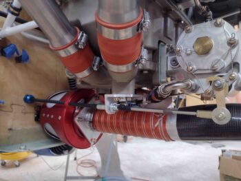
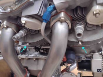
I then test installed the throttle cable on the other side as well. At this point I’m happy to report all looked very good with the cables as far as lengths, mounts and connections.
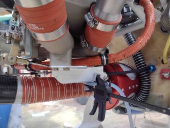
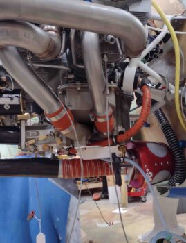
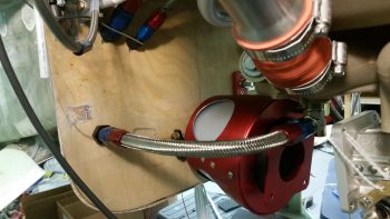
I did drop the throttle cable mounting tab down about 1/8″ further than I had planned since the clearance between the throttle cable arm and the fuel hose is a bit tight… around 1/4″
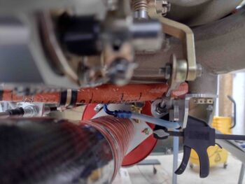
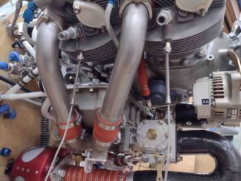
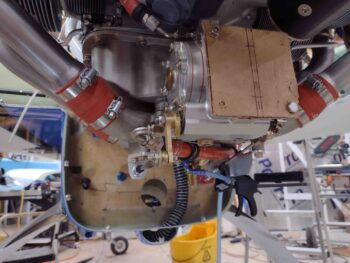
Here we have a shot from below of the throttle cable test install. Again, I haven’t encountered any serious issues, although there is a clearance issue I discuss below between mixture cable and the oil heat hose.
Here we have the 3 cables exiting the pilot seat bulkhead and all aiming for the pilot throttle quadrant. Again, I have the throttle and mixture cables that go all the way to the fuel injection servo on the engine and then a slaved throttle cable to the GIB throttle quadrant (see below).
I had planned on running all 3 cables through the one hole I had made, which is big enough for all to go through. The problem is spacing on the back side of the hole since 2 cables stacked vertically can wrap around the heat exchanger while a third cable jams everything up.
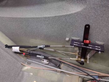
After scratching my head a bit, I simply drilled another hole down below and ran the GIB throttle cable through it. That put that cable low where I actually want it above the engine throttle cable, so I swapped it with the mixture cable (red tape band). Not to brag, but my measurements are so tight (we’ll call them “spot on”… ha!) that dropping my mixture cable down a couple of inches actual makes it almost an inch too short at the quadrant… how’s that for just the right length?? (whew!) Clearly, I need to swap the GIB throttle and mixture cable back to where they were previously.
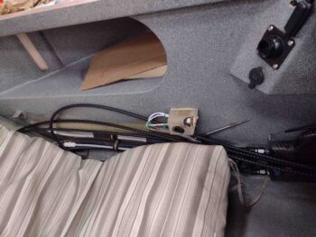
Speaking of the GIB throttle cable, here it is in the back seat. While I will convert the GIB throttle quadrant to a reverse configuration (pivot at midpoint vs bottom), I won’t be mounting the GIB throttle until the pilot quadrant cable installs are final.
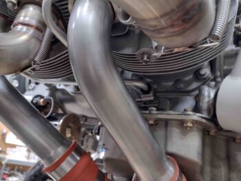
In finding the sweet spot for my mixture cable pass-thru on the firewall, one thing I didn’t address or take into account (not that it would have mattered… I’m fairly certain I would have pressed forward) was the oil IN hose for the oil heat system at the firewall. As I had the Bowden cable in place for the mixture cable test run, I realized that this interference between the two was most likely going to be a gotcha…
Here is an old pic from 2018 showing that oil heat hose in place. The mixture cable pass-thru is straight inboard of this hose and the lines do crash into each other (if both were installed concurrently) elevation-wise just aft of the RAM air can.
All part of the process eh? So I’ll have to do some jucking and jiving to fix the oil hose run with either new fitting angles, relocate it on the firewall, or both. The good news is that these are the last firewall pass-thru components to get installed (except for RAM air can lever below; accounted for) so it SHOULD be the last firewall relocation and/or manipulation that I have to do.
My last task of the evening was to remove the RAM air can to start making preparations for its final mounting (once the firewall covering is in place) and to modify the butterfly valve rod to add a lever arm that will actually transit the firewall via a small 1″ incision (aka “slot”) to be manipulated by a mini linear actuator inside the hell hole.
Back in the house I spent another hour plus taking measurements and assessing my plan for the final install and configuration of the RAM air can. Tomorrow I’ll be working a lot on the throttle quadrants in order to get the cable installation complete from A-Z.
Pressing forward!