
Today was all about ‘shoulder addition surgery’ . . . yeah, yeah, so it sounds like something “Doctor” Mengele would be involved with. Well, I can assure it is not! This is all about the glorious Long-EZ, not some debased science experiment! <wink>
I digress . . .
First off, after glassing the strake “stock” flange I naturally had a decision (or 5) to make: Do I add the follow-on Melvill CAMLOC lip as I did with the D-deck? Or do I do something else?
I chose something else.
I decided I would layup the “Melvill CAMLOC lip” all in one go from the strake flange that I had just laid up, around the “shoulder” and tie it into the D-deck flange.
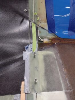
To do that I would need to venture off without having “gear adrift” (Navy term), as in I wanted to secure the outboard front edge of the top cowl. To do this I simply drilled a couple of holes in the now cured “stock” flange for a pair of temporary Clecos (these holes will be filled in during finishing).

I then marked each side top cowl “shoulder” flange for trimming.
I removed the top cowling, cleaned off the tape, and pulled the peel ply from the strake flange underside before trimming the flange at the cowl “shoulder” flanges (marked above).
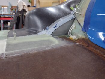
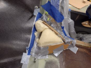
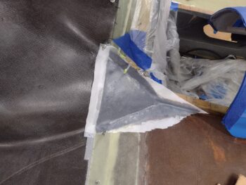
I then grabbed some cardboard and duct tape to make up some aft pour foam dam walls for the top cowl “shoulders”.
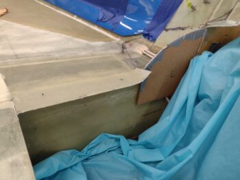
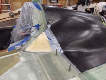
Here’s a test fit of the aft pour foam dam walls with top cowling in place.
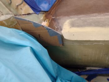
I then finished constructing the remaining part of the pour foam dams for both left and right top cowling “shoulders.”
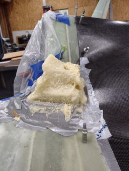
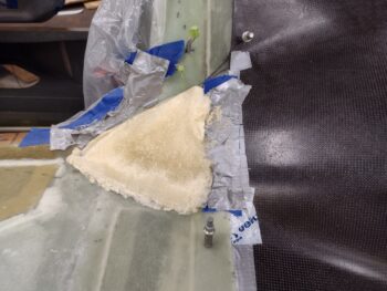
I then whipped up some pour foam and dumped it into the right “shoulder” dam… I was probably 1/8″ too shy in my inside cup marking to make a complete fill. As you can see by that top dollop I needed just a hair more pour foam juice to complete my mission on the right side . . .
The way to solve this problem is to of course completely over-compensate! The dollop to finish off the right side was from the left side pour foam application, which itself turned into a seemingly living creature… as it oozed out of the dam on the left side it decided to do a nose dive into my strake, which I thwarted. Thus why it looks so ugly because I ‘uprighted’ the foam overflow and stretched the curing glue component.
On the right side I judiciously lopped off the exposed foam and then ripped off the pour foam dam (feel free to picture Conan the Barbarian in this scenario… ).
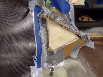
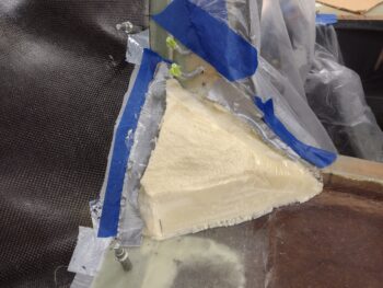
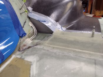
After a number of rounds of sanding, shaping and vacuuming [it’s an iterative process!] I got the right “shoulder” ready for glass/CF.

I followed pretty much the same process on the left side… slowly sanding and shaping the top cowling “shoulder.”
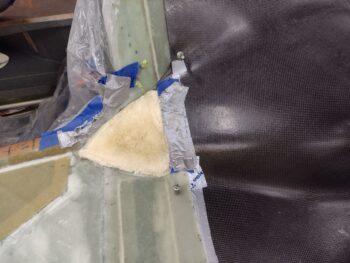
And finally getting it prepped for glass/CF.
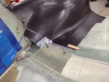
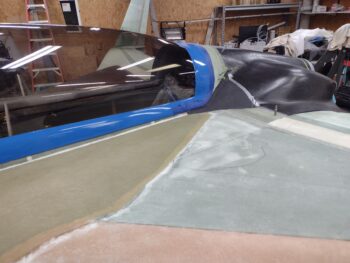
My layup schedule for the “shoulders” was 2 plies of BID followed by 2 plies of carbon fiber. One reason I’m using CF is that it is amazingly resistant to heat, and I plan on having a black accent line/swoosh —as I do on the bottom of the plane— that goes just a skooch onto the inside corner of the strake. Notice I stretched the top CF ply out to cover this corner just a bit to allow for that black paint.
I of course did the same thing on the right side.
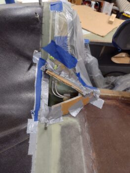
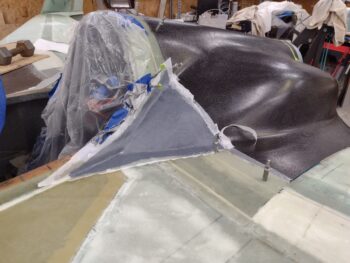
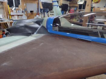
And here they are many hours later after I pulled the peel ply.
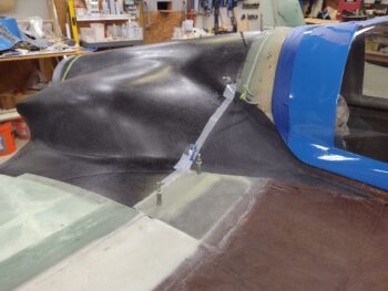
I guess with these shoulder fairings in place and their being black carbon fiber, and thus a bit harder to make out, it’s not so much what you do see but what you don’t: unfinished corners with bare fuel vent lines showing.
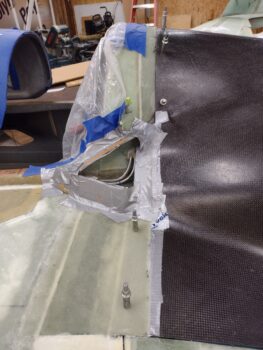
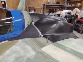
Here’s a couple longer view shots of the “shoulders.”
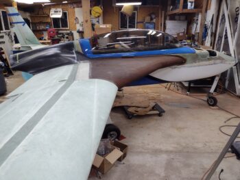
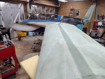
And I guess we can call these medium view shots. I have to say I’m really happy with how these top cowling shoulders came out.
Tomorrow I’ll continue on with the top cowling install.