
Today was all about finishing up a bunch of tidbit tasks to allow me to remount the engine to the fuselage.
The underlying reason my timeline for remounting the engine was hastened is in regards to my exhaust pipes. After communicating with Clinton at Custom Aircraft Parts and sending him detailed pics, including ones of the left pipes’ immobilization, he told me that he was ready for me to send the pipes to him to get tweaked… one at a time. Which makes sense since we’re doing this configuration tweaking remotely.
To be certain, after months of communicating on this back and forth, I am very appreciative that Clinton was going to do what he could to resolve these clearance issues.
However, Clinton’s caveat was that their current lead time on projects was 45-60 days. I totally understand shops being swamped with business, which is a good thing, but if we work these pipes one at a time, with the cost and time of shipping back and forth, this could be a rather costly endeavor that could potentially take 6-7 months longer. That timeline is a No-Go for me… so I had to find another way.
Enter local race car header builder James R. … through talking to one person after the next, who knew this guy, etc. I finally got James on the horn. His shop specializes in high end stainless steel exhaust systems for race cars, and he understands exacting tolerances… and more importantly: stainless steel. No disrespect intended, but unlike Clinton and gang who do aircraft exhausts as their bread and butter, James seems to be looking forward to a slightly different challenge and helping out on something that is unique to his world. Moreover, he’s 45 minutes away!
So here’s the plan: I am going to cut and set the pipes in place in-situ on my bird, tack weld them and then simply take them to James to have him weld one weld on each pipe and call it a day. To be clear, in January I spent weeks looking for a “James” in the local area and nobody knew anybody who had the high level of knowledge and experience that I was looking for… I guess round 2 of my search proved more successful.
Bottom line is I’m pressing forward, and am cautiously optimistic that within the next 2-3 weeks this exhaust pipe clearance issue will be a thing of the past.
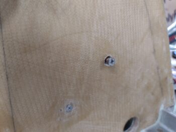
Ok, back to the current build. I started off by digging a hex-shaped divot into the firewall to mount a bolt/screw to allow securing an Adel clamp inside the GIB headrest engine components compartment. I floxed in the bolt, secured it on the other side and added a ply of BID over the bolt head. And then peel plied it.
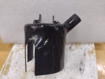
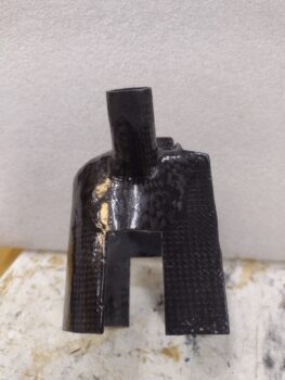
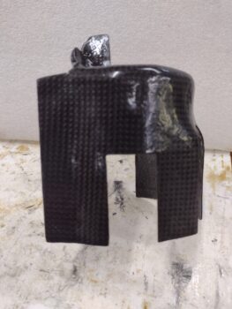
In assessing the “completed” fuel pump cooling shroud, there were 2 things I wanted to tweak. Both involved the air inlet nozzle. First, the CF at the joint between nozzle and body wasn’t as smooth as I wanted. Which I could have just used some micro to clean that up.
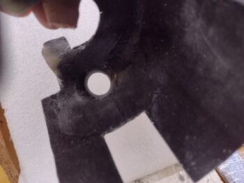
But second, although the 2 plies of CF for the nozzle seemed stiff enough, since I was going to be applying clamping pressure to secure the SCAT tubing to the nozzle, I really wanted a 3rd, internal ply, of CF. So I laid one up on the inside of the nozzle tube, which transitioned over the nozzle-to-body intersection as it overlapped onto the inside of the cooling shroud. I then peel plied this internal CF layup.
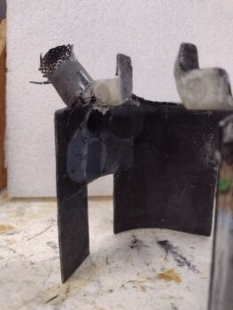
Here’s what that looked like after I pulled the peel ply and cleaned up the layup a few hours later.
While that last CF layup was curing, I also epoxy wiped the fuel pump cooling shroud with 2 rounds of West epoxy.
The epoxy wipes were simply to fill in any pinholes, etc. on the surface of the shroud. When I remove the engine next time I plan on wet sanding the excess epoxy off and either leave that if it looks fine, or maybe hit it with one final thin epoxy wipe or a coat of clear coat.
I’ll note that in its current state this fuel pump cooling shroud weighs in at a whopping 1.9 oz.
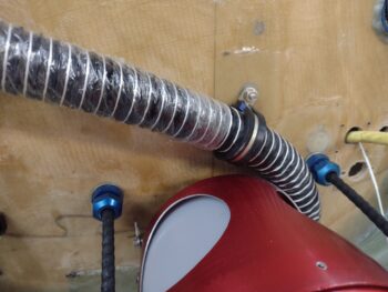
I also evaluated the SCAT tubing flow, both locally to the fuel pump cooling shroud and as part of the entire system beginning at the RAM air scoop-located NACA scoop. I added an Adel clamp to secure this segment of the of the SCAT tubing near the cooling shroud.
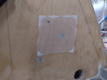
I also installed a Clickbond on the firewall for another Adel clamp to secure the SCAT tubing coming up from the NACA scoop.
I am mentally creating the “Y” joint that will attach this SCAT tubing to the pair of 7/8″ diameter SCAT tubes that go to the fuel pump and PMag for cooling (I actually laid up and peel plied a 1.5″ ply of BID on the end of the aluminum tube that will get attached inside this SCAT tubing and have the “Y” tubes attached to it… not shown).
I had printed out wire heat shrink labels a long time ago when working on the P9 and P10 firewall electrical connectors, and I finally heat shrank those 5 labels onto the wires tonight.
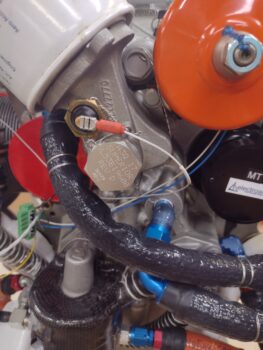
I also remembered that my Oil Temp sensor was installed only hand tight, so after some quick research on that I installed it to its “torque” spec (actually rotation spec on this guy: 135° after hand tight to properly seat the crush ring).
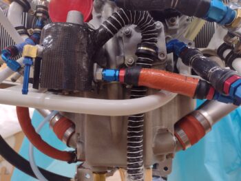
I then safety wired both the OT sensor plug and the cover cap on the mechanical tach port (top center of pic, in-between the white oil filter and orange SD-8 b/u alternator).
I had planned on Jess helping me with remounting the engine, but she got tied up a bit helping her grandmother so I pressed forward on my own. I figured since I may have to do it someday on my own anyway that this would be a good test of my abilities.
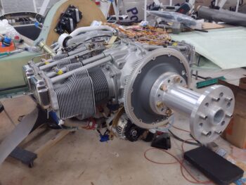
With the engine mount extrusions exactly the same distance apart as the engine mount nubs, I found the trick is to bring the engine down a hair low, angle it so the front is higher than the aft side and “hook” the lower nubs into the lower engine mounting extrusions. Then with constant forward pressure on the engine, raise it up and seat the top nubs onto the upper extrusions.
That worked a treat and I really had the engine on and initially secured in about 15 minutes. Add another 15 minutes to secure the hardware and I was done with the install.
I then checked the clearance between the fuel pump overflow fitting and the aileron torque tubes… a good 1/4″! Again, that equates to a mile in Long-EZ specs! <wink>.
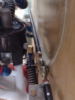
The same is true for the oil hoses, as I’m very happy with the clearance between those and the firewall as well. These are the last items I need to be concerned about clearance-wise between engine and firewall… hoo-yah!
Tomorrow I plan on getting to work on the exhaust pipes and hopefully get those clearance issues taken care of ASAP. As for now, Jess is making Keto-friendly tacos… time to sign off!