
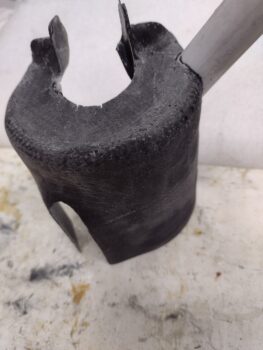
After a good overnight cure I pulled the CF/BID and its plug off the canopy sealing goop bottle… I then trimmed all the edges of the layup to clean it up.
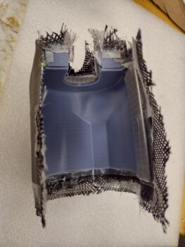
I then pulled the fuel pump cooling shroud off the plug…
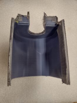
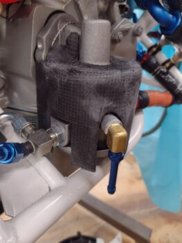
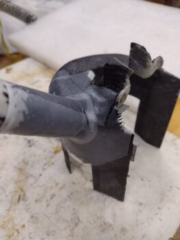
And pulled the inside peel ply to go a few rounds in creating the slots for the fuel IN, fuel OUT and overflow fitting bosses. I’ll note that this is another area where my roll-your-own design is different from Lycoming’s cooling shroud: theirs has holes that require the shroud to be mounted prior to connecting up all the hoses/fittings.
Here we have the last of the iterative test fits with the final trimming of the 3 slots complete.
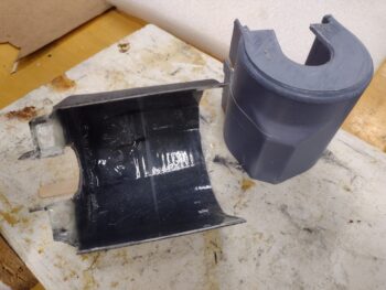
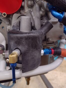
I then did some test runs of the 7/8″ diameter SCAT tubing to figure out where the optimum placement for the tube attach nozzle should be on the cooling shroud.
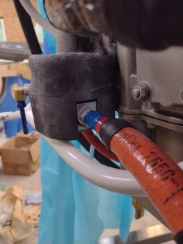
I had thought about coming in at a lower angle, but here I figured I should follow Lycoming’s lead with the air blasting at and pointing towards the main body of the pump: to optimize the effect of the cooling air flow. This required more of a 45° down entry into the cooling shroud… I’ll again point out that my tubing nozzle is about 180° out (port side) from Lycoming’s (starboard).
I used a length of thin-walled plastic pipe that I picked up in Germany for the plug to create the tubing nozzle. For the hole I simply drilled a pilot hole then used a 7/8″ diameter hole saw.
Before glassing up the nozzle, I made a slit down the length of the plastic pipe so I could collapse it for removal after the tubing nozzle cured. I then covered it with clear tape and peel ply before laying up 2 plies of carbon fiber. I of course completed the layup with more peel ply.
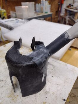
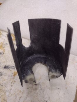
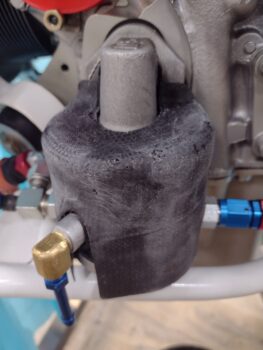
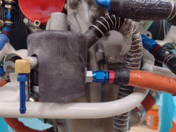
Here is the nozzle trimmed about 4 hours later, with the fuel pump cooling shroud back on the fuel pump.
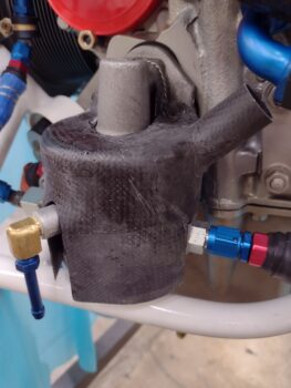
I then threw my SCAT tubing on the nozzle for a quick check and to show the configuration of my fuel pump cooling setup.
And with that, I called it a night.