
Since I returned from my vacation I’ve been working another round of all the small parts and hardware I’ll need to get all the myriad of components attached to the engine: Adel clamps, hi-temp Adel clamps, hose fittings, hose clamps, bolts with drilled heads, etc.
I dropped ACS and McMaster-Carr orders just before heading out on vacation, all of which were waiting for me on my front porch when I returned Saturday. Sunday I pulled the trigger on a piece of the plans called out 0.02 inch 301 stainless steel for the canopy safety catch SC-1 (I have a 304 SS piece on there but it’s too weak and flimsy for the job). I’ve also been working fitting assemblies to allow me to final pressure test all my engine fuel, oil and sensor hoses.
My next task on the list is to create the carbon fiber 180º air duct that mounts to the aft face of the aft-facing FI servo, loop around forward, then connect to the SCEET tubing attached to the bracket that I just machined. I’ve spent the last couple of days doing more research and some cross-checks required before I go hot with making the air induction tube, and am hoping to start construction in the next day or two.
My research has included multiple hours of Fusion 360 instructional videos since I clearly need some “Continuing Education” credits (or remedial training?!) to brush back up on modeling parts in Fusion 360 CAD.
Well, I’d say the extra training paid off. It increased my CAD kung-fu at least to a point that allowed me to much more efficiently and gracefully create a CAD model of my Fuel Injection Servo air intake duct. After fumbling around with it in the manual cardboard mockup arts ‘n crafts style, which is often fine, I simply needed a way to allow me to tweak the configuration and then fine-tune it.
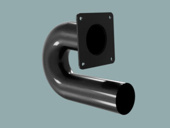
That led to this:
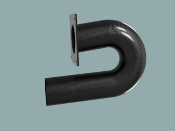
As per the rendered model, this part will in fact be carbon fiber. Much like the Fuel Injection Flow Divider (aka “spider”) bracket that I produced 5 versions of, this assembly will also get 3D printed until I get the version that fits optimally with decent clearance with the bottom cowling. I then plan on using the final model version as the mold to create the FI servo air duct.
It’s quite late here, and it’s been a long day of learning and then implementing my knew-found CAD knowledge to allow me to model up this part. Tomorrow I’ll begin 3D printing it and press forward from there.