
I’m going to run through these pictures below regarding the machining of the RAM air can SCEET tubing adapter bracket —that I finished machining today— quickly since there is a video covering all of it below.
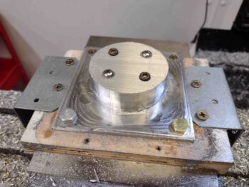
I completed Phase 1 of the machining yesterday, albeit not without slight incident. Phase 1 was the facing of the forward face that interfaces with RAM air can plate. I also machined (or drilled via the mill) 4 holes to mount the bracket assembly to a plywood base to allow me to finish the rest of the machining process on the side opposite of Phase 1.
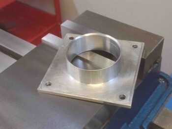
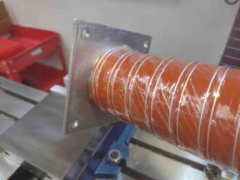
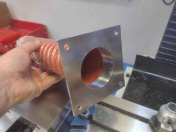
Here we have the bracket assembly at the end Phase 2, which is the external side of the tubular SCEET tubing adapter and the mounting flange of the entire bracket.
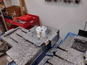
Here’s a closer look… note a 0.264″ diameter hole in each corner.
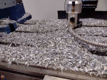
Also note the mess that milling away that much aluminum makes… honestly, it seems like kind of a waste. But parts are needed!
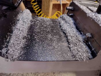
Here’s another giant pile of aluminum chips.
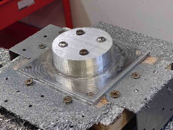
I then bolted down the front corners and screwed down the aft corners to the plywood milling base.
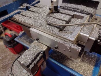
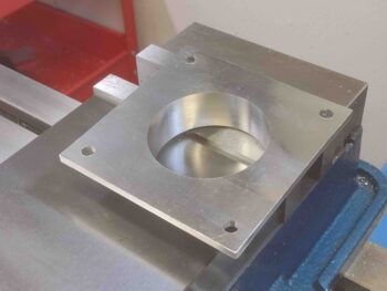
I then removed all the hardware from the middle and commenced Phase 3, which was to create the hole in the middle and walled tube adapter.
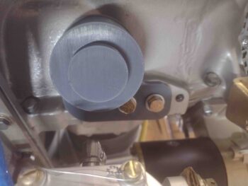
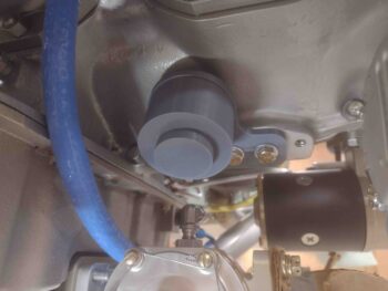
I then checked to see if it would actually work, and Voila! It did. The SCEET tubing fits snugly enough on its own to the bracket that I don’t need to hold it in place.
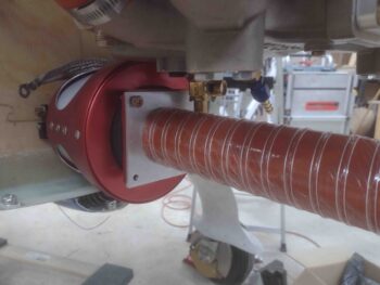
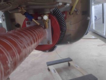
I then I temp mounted it onto the RAM air can just to get a quick idea of the clearance. Note that after everything is installed, and the engine quick oil drain torqued to specs, I’ll most like trim it at an angle to allow clearance of the SCEET tube but also to still be able to slip on a plastic tube for draining oil during oil changes.
Ahh, and here we have the much awaited, critically acclaimed (not really) video… enjoy!
The very last thing I did before heading out the shop door for the evening was mount the fuel injection flow divider onto the new, rounded-corner Version 5 bracket and mount it in place on the underside of the engine.
This is the final bracket version I plan on doing, and I will use these 3D mockup to confirm the stainless steel fuel injection line lengths required for mounting the fuel spider on the underside of the engine. These lengths will be annotated for future use, and to be clear: barring any significant apparent operating deficiency, I do intend on flying this bird for at least a year with the fuel spider on the top side of the engine.
Why? Because I truly want to know for myself the operating differences between having this fuel spider on top vs the bottom of the engine. Call me a myth buster or a fool, no worries. But I do want to know.
Tomorrow I’m heading off on a cruise to the Bahamas with my girl for almost a week-long trip (her Christmas present to me). So Bon Voyage and see ya’ll when I return!