
My primary goal today was to produce a usable plug to use in glassing (mainly carbon fiber) a cooling shroud for the engine mechanical fuel pump.
As with many of my self-designed parts, this was definitely an iterative process.
This is the point I got to late last night as I kicked off the 3D print for this guy below. That print took nearly 3 hours and it was still whirring away as I went to bed.
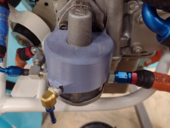
This morning I test fitted it. Although I clearly thought I had nailed the side protrusion that allows the fuel pump overflow fitting boss to fit under the cooling shroud, I was off by about 0.12″ each side.
It took about 3 more prints to dial this in and then pretty much a remodel in CAD to get the final product. I kicked this nearly 5-hour 3D print off early evening and made some much overdue phone calls (as well as dinner) while it printed out.
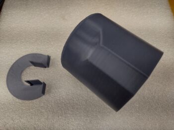
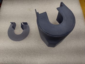
In all actuality, I designed, CAD modeled and printed the small top cap piece first since it only took about 30 minutes to print and then verify fit. Then I kicked off the big mo-jamma plug.
The reason for the separate pieces is simply for ease of 3D printing. The big plug is much easier to print with the flat top down and then simply have the sides build up. The same too in the inverse for the top cap with the tabs that are sticking up.
I had wanted to get this piece glassed up tonight, but with the multiple versions and the long print time, it is what is. My plan is to glass this first thing tomorrow and get on with other engine tasks.