I started off today with a couple hours of research. Although the weather was forecasted to be significantly warmer than yesterday, I figured I would wait until the afternoon to start work in the shop to let it naturally warm up a bit.
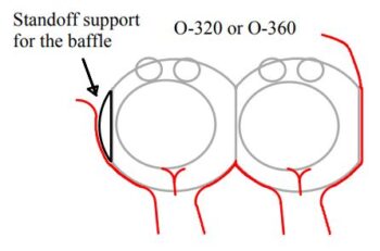
My research focus was on something that Andreas Christou discusses in his article, Design for optimal cooling efficiency, where he points out that the design of Lycoming type cylinders leaves the front of cylinder #3 and the aft side of cylinder #2 with virtually zero depth on the cooling fins (in a small area it’s literally just flat). His suggestion as depicted in this diagram from his article (and yes, it’s upside down for us Canardians) is to create a standoff on the cylinder to extend —or literally create— the fins to support the baffle along that segment of the cylinder.
I had a discussion on this with Mike Beasley over lunch when he and Marco came down to visit me and Jess. He mentioned that Dave Anderson had done a “washer trick” or something to create a gap on the #2 cylinder to account for this issue, and that Dave had purportedly resolved his hotter #2 cylinder cooling. I’ll further note that from my gathered info, from accounts of other pusher drivers, and specifically from Mike and Marco at lunch: cylinder #3’s CHT on our birds doesn’t seem to suffer from a lack of a standoff. We concurred that it was most likely since it was just aft enough and in direct line of the incoming cooling airflow, both on NACA and armpit scoop cooled EZ’s, that it seemed to cool as well as the other “tamer” cylinders.
A couple days ago I hit up Dave Anderson on FaceBook to ask him “How he done it?!” He said he was heading out to the airport in a day or two and would grab me some pics of what he had done to resolve this issue.
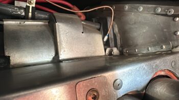
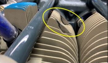
Here are the pics that Dave grabbed for me showing his cylinder #2 aft baffle configuration. Note that the outboard baffle is simply off/away from the cylinder fins by about 3/16″.
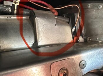
And here’s a closer shot of that standoff. I asked Dave the difference it made and he said it was considerable, about 100° F cooler for that cylinder. Pretty impressive in my book!
Then, as I was perusing through the earlier issues of the COBA Canard Aviation Magazine this morning, mainly looking for Steve Beert’s excellent write-up on the engine inner baffles, I ran across an article by Dave Adams from April 2021, Issue 142, that showed what he did to resolve/mitigate this cylinder #2 standoff issue. Funny thing is when I first started looking at the article I just quickly noticed the name and thought, “Dave wrote an article on this, why didn’t he just tell me to read it??” After another look I realized it was Dave Adams. Oops! (So many Dave’s in the canard world, eh?!)
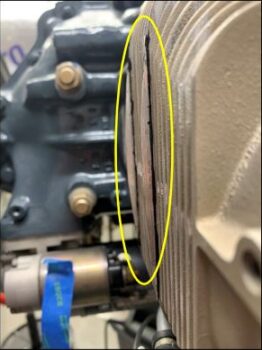
Here’s a shot out of that article of some thin standoffs Dave added to the aft side of cylinder #2 to create the standoffs I’m talking about.
Moreover, Dave Adams solved another head-scratcher for me as well with the depression in the fins at the top of all the cylinders. When the baffle covers this part of the cylinder fins, clearly it lets air escape out the sides. Dave added mini walls at the outboard fin on each side to keep the cooling air channeled in the middle. Quite smart and I intend to follow suite… because as we all know, any extra bit of cooling we can get on these birds —without adding drag!— is golden.
At this point in the day the weather had warmed up a good amount, so I headed to the shop to do Round 2 of the 2-ply CF layups on the inner baffle forms.
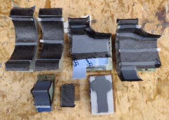
Starting in the top left corner in the pic below are the final 2 base cylinder (inboard) baffles [I have a surprise reveal on these and the other cylinder #1 aft baffle <far right in pic> tomorrow!].
The baffle form in the center of the pic with about half of it covered with the CF layup is the first of 4 of these separate cylinder “end” baffles that will get paired off and combined back-to-back to make the top outboard center baffles.
Finally, along the bottom row we have the second set of the bottom inter-cylinder baffle (V shape), the top inter-cylinder securing angle bracket (L shape), and the top inboard inter-cylinder baffle plate (cross shape).
After adding some peel ply I then left this round 2 set of inner baffle layups to cure overnight.

