
Today was all about engine baffles. I had tried to get to the lower cowling intake ramps and inboard intake wall, but I just ran out of time.
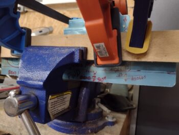
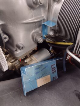
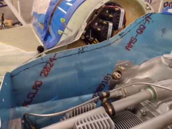
My first task was to evaluate, assess and mark up the bracket that secures the center forward baffle wall to the front centerline engine crankcase bolts. The issue that I showed previously is that cylinder #4’s stainless steel fuel distro line is in the way of installing this bracket sans modification.
Below are my chicken scratch trim markups.
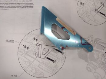
After a couple rounds of trimming I got to this point below. Yeah, maybe not the most “normal” looking bracket, but it will certainly work. The fuel line in the pic looks as if it’s almost touching the bracket, but it is well away from it, and I will certainly ensure that the fuel line is nowhere near this bracket.
I took a bunch of pics of my work on straightening out the slanted left aft intake ramp that would normally be the “floor” of the cowl air intake scoop on an RV tractor aircraft. But as I was loading up my pics I realized I didn’t have a good “before” shot of what I was working on… so I added these shots from the VAN’s baffle kit install manual.
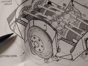
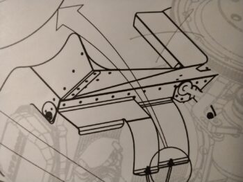
As far as this intake ramp goes, I want to turn it into the aft shelf (horizontal) & skirt (vertical) that makes up the aft segments of my baffles. Moreover, I don’t want this part slanting down, but rather straight aft from the angle support bracket that you can see just in front of each cylinder in the drawing above. Besides adding a bend to this baffle segment, the tractor motor configuration adds in a corner fillet… remove all that and that’s the part I’m dealing with here.
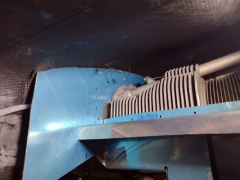
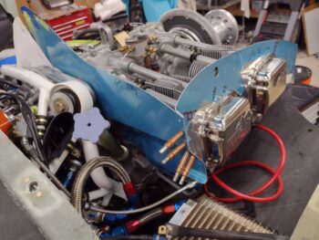
The underside of this piece has the 2 inboard baffles that wrap around the bottom inboard half of cylinder #1. In the pic below there are really only 3 baffle segments: the left side baffle on the outside of cylinder #1 (with its extended forward wall), the upright flywheel shroud (that has an ‘X’ through it because I’m not using it), and then the part I’m working on: the aft left baffle segment.
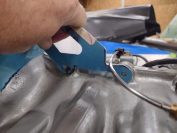
And here it is engulfed in wood as I’m using the old school method of straightening out the angled aft portion that the RV bubbas use as their intake ramp. I will note at this point I had already went another round of shortening the “ramp” portion that extends aft, using my Skil saw outside.
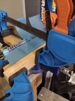
That trimmed portion is peaking out below the 1x2s that I’m using to protect the aluminum as I remove the angle. My loose-knit plan is to make the shelf out of this existing piece, create a tab on the aft side of the shelf, then make and attach the aft skirt to the shelf tab.
If you look closely you can see a red line across the bottom of the lower section peeking out, about an inch up. That will get folded over to make the tab…
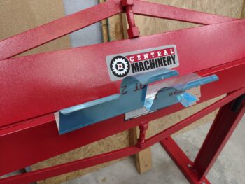
. . . using the newly assembled metal brake. The only problem was that I couldn’t get a good throw out of the brake to create a 90° tab because the two curved cylinder baffles were acting like springs and preventing me from creating the full, complete tab. So back to the vise I went to complete that task as well.
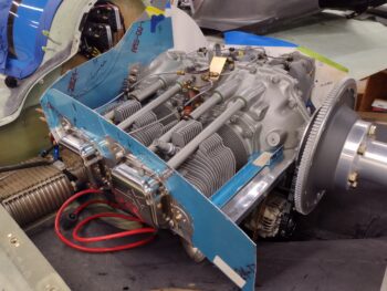
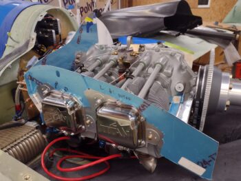
To mock up this aft baffle segment piece I needed to support it. But as things go when you try to mod a plug ‘n play kit the actual left side support tab was meant to be installed at an angle, so I had to use the right side engine tab here on the left.
The final installed support bracket will be from Mike Beasley’s Baffle templates.
And vice versa on the right side of the engine, where I temporarily have the left support tab in place.
On the right side this temp tab will get replaced with the Melvill style support bracket.
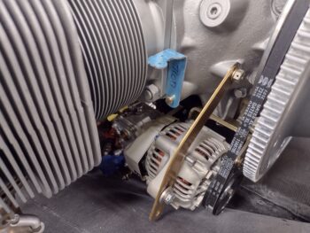
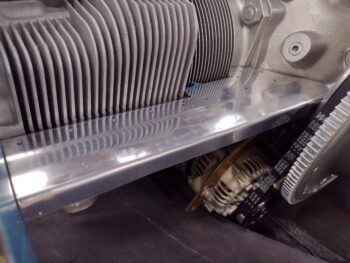
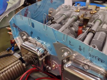
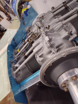
Yeah, she won’t win any beauty contests, but my plan to convert this aft left baffle segment did work. This is the “shelf” part, and along that front tab hanging down will attach the “skirt” part of the aft baffle wall… that’s if I actually use this part. I may very well create a whole new one-piece shelf and skirt for each side that meets in the lower middle of the skirt (between the alternator and starter). I’ll assess and ponder on this more.
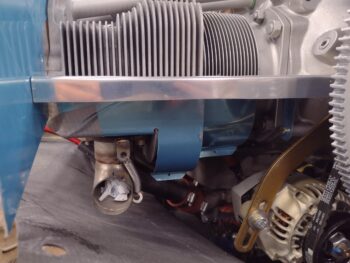
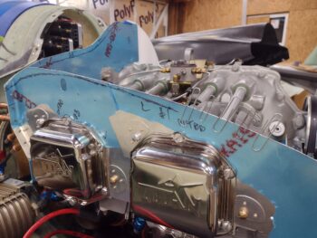
And here’s a shot of the lower side of the aft left baffle segment. Hopefully this will make the previous drawings make a bit more sense. Again, I’m still in the data collection and assessment phase as I am figuring out how I will incorporate the CF baffles, the shelf & skirt final configuration, integration, etc.
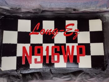
Earlier I had taken the aft nose/avionics cover outside to re-shoot the black paint with a couple more coats. A few hours later it was dry so I brought it back into the shop.
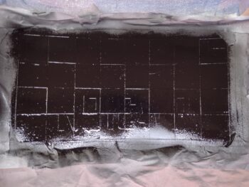
I took a small detour for some arts ‘n craft bit of fun, spending the next half hour pulling the protective tape squares off the cover’s inside panel, and then pulling the vinyl lettering off to expose the red painted characters underneath… again, pretty much as I did on the landing brake.
Now is where the work really begins as I’ll need to take 2-3 hours to manually touch up all the edges of the white, black and red paint. After all the touchups I’ll then clearcoat this painted panel. For now I’m going to let this thing cure a good 48 hours before I do anything else on it.
I then did yet another round of height trimming on the left side baffles: mainly the front corner and a few spots along the front wall.
After trimming the pieces and cleaning all the dust off, I then remounted the left-side baffles. Finally, after a number of rounds of baffle trimming, I had enough clearance to allow me get the top cowling fully mounted back in place.
I then used the paperclip trick to determine the final height. Since I could only round up a few paperclips, I did the front side first (pic 1), and then the back side (pic 2).
Again, although not elegant in appearance, the paperclips did allow me to determine the gap height and thus the required amount to trim off the baffles.
I didn’t use paperclips on the front wall, but rather peeked in the back of the cowling and through the oil check door hatch to determine the required trim line.
Since the Long-EZ plans describe the process for installing baffles for an O-235 engine, I wanted to do a final crosscheck on the gap required between the aluminum baffles and the inside of the top cowling. I sent out a flurry of text messages to a bunch of my canardian crew to figure out the best gap. Well, I found out a few key pieces of actionable intel, but not a definitive answer on the gap.
I decided instead of the 3/4″ that the plan calls out (in general), that I would narrow the gap to 1/2″ (which is what is in the VAN’s instruction manual). Clearly it’s just a matter of time to hack off another 1/4″, but adding a 1/4″ back on is a little problematic!
Here we have the “final”-trimmed left engine baffles.
And the requisite inside shot as well.
And let’s not forget from the front!
Ok, too much thinking today… and more tasks added to my list, that I’ll discuss over the next few days. For now, I’m calling it a night!