So one of the things I was educated on as I was querying my posse of canardian buddies on what might possibly be the optimal “modern” O-320 baffle-to-top cowling gap size, was a throwback feature right out of the plans that was implemented by a few of them:
The top cowling 4-ply rib baffle that creates a mini-baffle hanging down from the top cowl just inside-adjacent to the cylinder baffles. Intuitively I would think that these ribs are no longer needed, but I know the Long-EZs that these are installed in and they tend to have great cooling… so I’m adding these rib baffles to the mix.
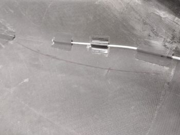
I started by reaching up into the cowling and marking a line along the edge of the left cylinder baffles onto the underside of the top cowl. I’ll do the right side as well after the side baffles get cut and installed.
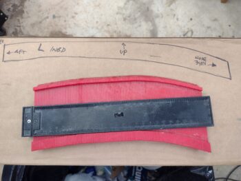
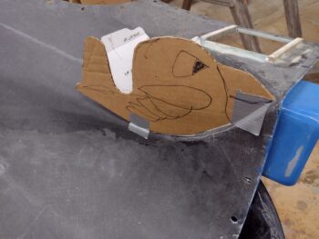
I then used my contour checker to create a template on cardboard that looks suspiciously like the one right out of the plans (for a different top cowling of course).
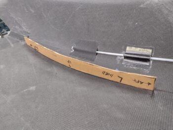
I then test fit the template and did a few rounds of trimming it for a good fit against the top cowling.
With the top cowl installed, I then tried using tape to secure it to the inside of the top cowling, but that wasn’t working well. I decided to follow the plans even more specifically and make a wood version of these rib baffle templates and then hot glue them to the top cowl for a better fit. I’ll probably make these up tomorrow.
Back on the baffles, I added a bit of height to the right side baffles to target about a 1/2″ gap between baffle top edge and inside top cowling.
After the right side cylinder baffle heights were tweaked —with a few rounds of top cowl on and off— I then started filling in the baffle-to-cowl gaps along the right front baffle template segments.
After feeling good about the gaps I marked and trimmed the right side cylinder baffles and mounted them.
And then followed suite on the inboard right front wall baffle segment: trimming it and mounting it.
I’ll note that in following the VAN’s baffle kit plans I cut a 7/8″ length off an aluminum tube included in the kit to mount the inboard right front wall baffle segment to a hole in the engine flange 2-3″ inches below the right top engine mount bolt. This spacer seemed about 1/8″ short, so I’ll reassess what the required length/gap here needs to be.
With the right inboard front wall and right cylinder side baffle segments in place and fitting well under the installed top cowl, I then mounted the final front baffle wall piece on the front outboard side with clecos… along and just forward of cylinder #3. I then marked it for trimming as well.
Here we have the last baffle segment for the front baffle wall, adjacent to cylinder #3, marked for trimming.
I then removed, trimmed and remounted the outboard front wall baffle segment. I checked its fit by remounting the top cowling and although it needs some height tweaking —as all these right side baffle segments do— it fit fine.
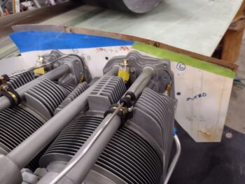
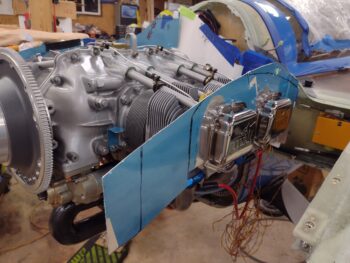
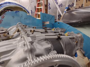
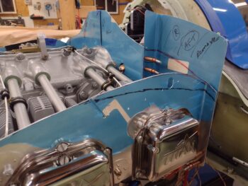
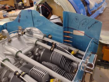
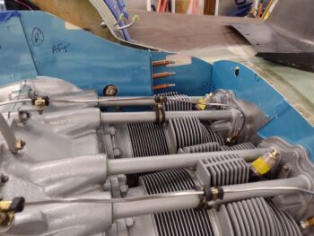
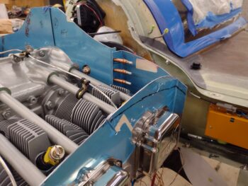
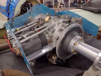
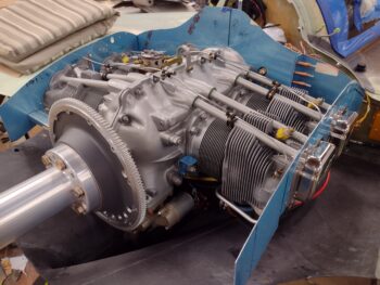
Here we have the front, left and right engine baffles mounted and trimmed to fit under the installed top cowling. Again, although the baffle heights and gaps between them and the top cowl need to be tweaked and refined, there aren’t any baffle top edges touching the inside of the top cowling, nor are there any egregiously wide gaps that will need to be filled.
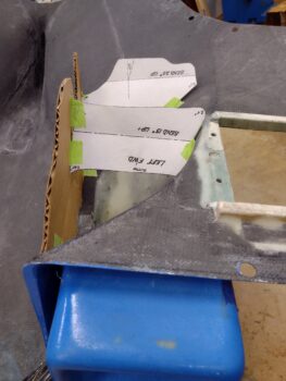
With the initial baffle mounting out of the way, I then got to work on the left side bottom cowl intake inboard wall and air inlet ramps. I taped them in place to mock them up… I could see the outline of a plane/bird so I took a minute to have some fun with that.
Here are the inside inlet ramps taped into place. These cardboard mockups clearly include the top angled portion for each ramp, which I have yet to make out of aluminum (although I did already trace out the ramp top sections on scraps I cut from the baffles). In fact, I won’t cut these aluminum top pieces of the ramps out until I have thoroughly mocked up each side and determined the final configuration for each ramp.
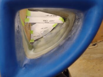
This shot through the armpit inlet gives you a really good idea of what this “inboard wall” and “air inlet ramps” business is all about. The wall keeps the incoming air wrangled to channel it through the ramps: the front/top ramp sends air up through the front cylinder (#3 here) while the air that passes underneath the front/top ramp then gets to the aft/bottom ramp that sends air up into the aft cylinder (#1 here).
Again, this is how Mike Melvill configured his air intake ramps and he got some really good cooling numbers with this design (remember, Melvill was working with Dave Ronneberg who was advising him on how to implement Berkut-style armpit cooling on a Long-EZ… something that had never been done before).
I tried to install the bottom cowling with the left inlet mocked up as you see above, but it just wouldn’t go on. I had to disassemble the mockup and reassemble it once the bottom cowling was on.
That being said, understandably I can’t just simply implement Mike Melvill’s configuration on my bird. With my cold air induction pipe locations and in-cowl setup somewhat different than Mike M’s, I’ll need to tweak the ramp positions a bit… not much, but probably in positions within 1/2″ of his.
Although I did some trimming on the inboard wall cardboard template, my main task was simply “observing” how the air would flow into the intake and down the chute. I spent a good half hour just looking at and assessing my air intake flow and realized something pretty cool: the position of the top ramp captures the air and directs it into the front cylinders before the air hits the front round cold air intake tube, thus pretty much negating any blockage of airflow from the front intake tube. Plus, a round shape is horrible in creating turbulent air. Even better, downstream the same thing holds true for the relationship between the aft/bottom air ramp and the aft cold air intake tube. The aft/bottom ramp blankets the air flow that would normally hit the aft round air intake tube and directs it up into the aft cylinder.
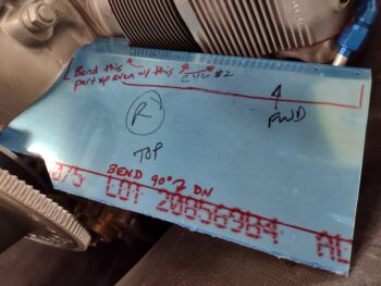
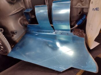
Satisfied with my recon and intel collection on the air intake inboard walls and ramps, I then started assessing my aft engine baffle areas. I have yet to straighten out the angle on the right aft baffle “shelf,” but at least I’m getting a BEFORE picture of it here.
BTW, here is an underside shot of the aft right baffle section. Part of my assessment as I gear up to make an entire cylinder baffle kit out of CF is whether I’ll use the baked-in lower cylinder baffle tabs… obviously integrated into these aluminum baffles.
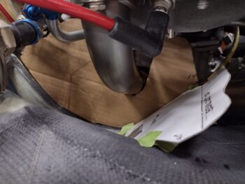
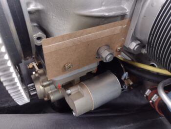
I then grabbed a scrap piece of cardboard to make a mockup to test out my aft right baffle Melvill “shelf” bracket configuration. On Mike Melvill’s diagram he has the distance between the 2 screw holes as ~4″ where in reality the actual specific dimension is 3.88″. Also not depicted on Mike M’s bracket diagram was the giant engine bolt that protrudes through the bracket that needs to be accounted for.
Somewhat like the recon and assessment I did on the bottom cowling air intake setups, I spent nearly an hour here taking notes and figuring out how I’m going to install the aft lower baffle skirt that needs to wrap around the alternator and starter without intruding on the alternator belt pulley.
My final activity of the night, just out of curiosity, was to find out the difference in weight between using CAMLOCs on my cowlings vs screws. I thought of this when I picked up my cowling hardware holding card with a full load of CAMLOCs in it. Well, after weighing all my CAMLOCs and weighing a K1000-3 platenut, a -10 screw and Tinnerman washer and multiplying that weight sum by the number of CAMLOCs I’m using, the grand total difference is about 4.5 oz. more weight with the CAMLOCs. For those that are interested.
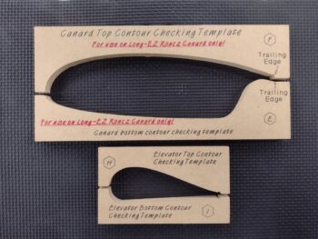
It was very late so I called it a night and closed up the shop. On my way back to the house I checked the mail… Lo and behold I got my Eureka CNC canard and elevator templates from Curtiss! Curtiss was nice enough to send me just these templates since a bunch of my 1/4″ plywood templates got drenched during Hurricane Dorian.
Pressing forward!

