
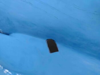
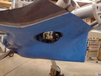
I started out today by creating a notch on the right side of the lower cowling, just aft of the armpit intake, to create clearance for the engine’s aft right cold air induction pipe.
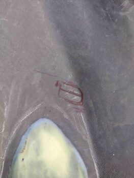
Of course this was NOT a one and done task, requiring iterative trimming of the right side lower cowling notch. Here we have the notch edge marked for further trimming.
And here we have yet another round of trimming on the right side of the lower cowling to again allow clearance for the aft right cold air induction pipe. This however, was not the final round of trimming.
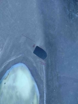
Much later, I did the final trim on the cold air induction pipe clearance notch.
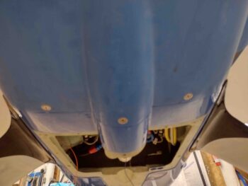
All the above notch creation allowed me to FINALLY fully mount the lower cowling with every CAMLOC installed. Here’s the left side . . .
and the middle bottom CAMLOCs, and finally the right side.
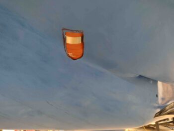
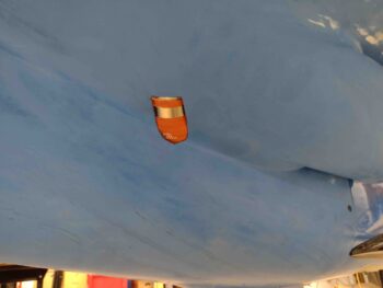
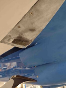
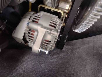
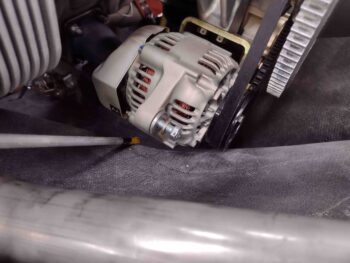
Again, since I’ll be tweaking the lower cowling on the right side, I’ll be removing the bump on the aft left side of the lower cowling for the alternator. I started the “bumpectomy” by drilling 3 small holes at the vertical outboard left edge plane of the alternator (pic on the left). To be clear, the “corner” break at the lower vertical to upper horizontal seam (right pic) will be left in place.
Here is the alternator bump on the aft left side of the lower cowling, marked for removal.
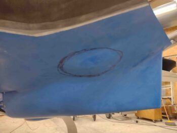
Which I did when I made the final trim on the right side for the aft right cold air induction pipe.
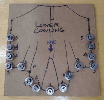
I’ll note that before I remounted the lower cowling this last round, I went ahead and made up a hardware card to allow me to keep track of all my CAMLOCs and screws.
Part of my efforts to correct and tweak all these engine components vs lower cowling interference, found me on the phone with Don at Airflow Performance in regards to swapping out my 85° elbow for a 90° elbow.
I also spoke with Allen at Precision Airmotive regarding clearance issues and configuration of the Silver Hawk EX fuel injection servo.
Finally, I spoke with Clinton at Custom Aircraft, who made the exhaust system for my bird. In my discussion with Clinton, we came up with an initial game plan for me to send the exhaust pipes back to Clinton for him to cut and re-weld at the proper angles to have acceptable pipe clearances as they exitf the cowlings.
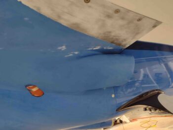
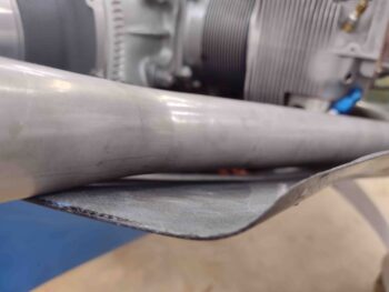
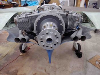
Here is another shot of the right exhaust pipes’ clearance with the lower cowling.
Although at angles, these pics show both the clearance of the exhaust pipes with the lower cowling, and also the left-right position so that the midpoint of each pipe pair is about 9″ from the engine centerline.
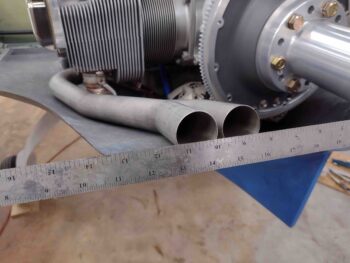
Here is a shot of the engine and exhaust pipes from above.
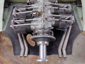
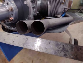
And from behind… I took these shots specifically at Clinton’s request to allow him to evaluate my exhaust pipe situation.
Tomorrow I plan on pressing forward in working both the lower cowling vs engine component clearances, along with some final winglet/rudder tasks.