
I started out today actually redoing yet another round of updates on some wiring diagrams, since I had switched around some remote functions on the GNS480 handled by the 5-way castle switch. I wanted to get the diagrams updated ASAP to reflect the changes before heading into the shop.
The weather was unexpectedly sunny & nice, so I took the opportunity to cut 4 beveled plywood hard points to reinforce the aluminum threaded inserts that the throttle quadrant will mount to. I then rounded the corners with my sanding block.
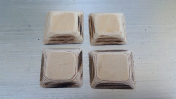
A bit later I drilled the appropriate size holes and then trimmed the top 2 plywood hard points… this throttle quadrant is marketed more towards RV bubbas so it mounts a bit odd going into a Long-EZ with the top mounting bolts almost even (but maybe 0.050″ low) with the top of the throttle quadrant plate. Not a huge issue, I just either had to trim down my top hard points or have to deal with them sticking above the top of the armrest.

To be clear, I had sat in the pilot’s for quite a while in an attempt to ascertain the right spot (for me) to mount the throttle quadrant. Since I’ll have to redo the actual lever for the throttle handle I have some flexibility on the height and left/right position of the handle, thus the main issue to determine today was forward/aft positioning and did I want it sunken a bit below the surface of the armrest or not [I chose not].
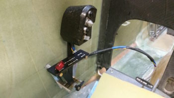
This pic below jumps ahead a bit after I had decided where I wanted the throttle quadrant mounted and subsequently after the holes in the left fuselage sidewall were drilled. I set the throttle quadrant threaded aluminum mounting posts into the holes, climbed in and ensured that this is where I wanted it before I finalized the install. I did move it forward 0.4″ from my originally planned mounting position. As you’ll note by the pics below, obviously I liked this spot so I pulled the pressed forward with the install.
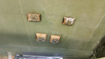
I prepped each threaded aluminum insert by taping up the outboard (open) ends of each one, and then bolting a tape-covered washer to the inboard open hole. I then mixed up some flox and started by floxing the threaded aluminum inserts into each plywood hardpoint. I then floxed the threaded insert/plywood hardpoint assemblies into their respective holes. Of course the back (outboard) side of each plywood hardpoint was slathered with flox as well, providing a fair amount of surface contact area for added strength.
[In hindsight, if I had really taken note on how close the bottom 2 hardpoints were together, I might have just made one longer plywood hardpoint. No worries though since what I used below worked fine too.]
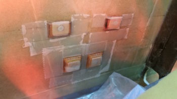
While the floxed-in threaded insert/plywood hardpoint throttle quadrant mounting assemblies cured, I then prepped the layups by cutting and prepregging 2-plies of BID for each hardpoint.

After the flox cured the majority of the way, I then mixed up some more epoxy, wet out the prepregged 2-ply BID layups and went to work. Here you can see all the threaded insert/plywood hard points glassed and peel plied. I then set a heat lamp on them (….my shop was a balmy 66° F).
It was getting late so I left the threaded insert & plywood hardpoint throttle quadrant mounting assemblies alone to cure in peace while I went upstairs to get a bit of research in. Tomorrow I’ll mount the throttle quadrant and dial in its exact, final location (left to right) in the left armrest console. Then I’ll start the process of building out the left armrest as I install the console internals as well. Again, this is still all part of the quest to get the lion’s share of the internal fuselage/cockpit components installed so that I can then install/construct/glass the firewall, nose & canopy.