
Today I started off by calling the folks at EFII to query them on my options for mounting my EFII fuel pump. In my research on fuel pumps, the position of the pump in relation to the fuel IN feed line is important, with a general requirement that the fuel pump be situated at a lower point than the IN fuel feed. Since I was thinking about mounting the fuel pump directly to the bottom of the CS Spar in the hell hole, I wanted to make sure I could do this without violating any conventional wisdom mandates. Well, as it turns out –and this is directly from the EFII horse’s mouth– it doesn’t matter the elevation of the pump vs the feed line, as long the pump is mounted horizontally.
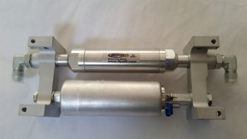
Still, after taking the pump down to the shop and mocking it up in a few locations, I decided the hell hole was going to be a crowded place, both in components making their residence there and with all the transient elements (fuel lines, cable antennas, wiring, cables, etc.) coming and going, let alone the exact space required for my RAM air intake. So I decided to kick this fuel pump can down the road and wait until I get closer to HAVING to install it.
Another sideline question that I asked yesterday, and got a response on, was from the folks at Radenna SkyRadar. I asked a couple of questions on their SkyRadar-DX
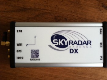 ADS-B receiver that I’ll be using: First, I wanted to know if I could mount the GPS antenna puck directly on top of the unit (I can!) and, second, I wanted to know if I could get a shorter GPS antenna cable (I can’t). Alexey from Radenna explained that the long GPS cables are pretty standard, and the reason for it is to provide proper attenuation for the LNA which is inside the unit. He also explained that it is possible to find an antenna with a shorter cable, but not in such a small form factor as the one that comes with the SkyRadar-DX. He also provided this helpful link from MGL explaining how to coil up the GPS antenna lead.
Clearly gathering intel is good, but actual work needs to be done! My first task of the day was swapping out the longer AN4-22A axle bolts on the left gear for the shorter AN4-21A axle bolts like I did on the right side gear leg. This didn’t really take long, but eventually I did have to remove the brake assembly to get to the axle bolts (remember this key point!).
Actually, I was able to swap out 3 of the 4 axle bolts, but I just couldn’t get a wrench on bolt head of the aft bottom axle bolt (it sits right next to the axle… too close for a socket).
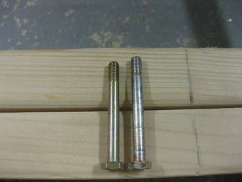
Here’s a shot of the axle bolts: new AN4-21A on the left and old (longer) AN4-22A on the right.
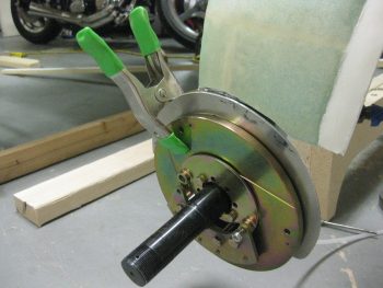
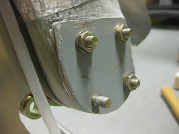
You can see the last holdout below, the whole reason why I had to remove the entire brake assembly (again, remember this point!).
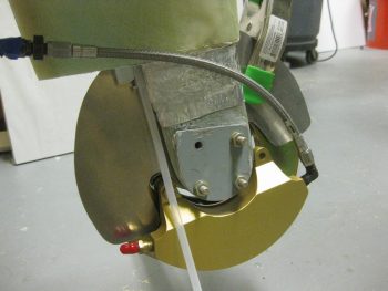
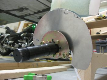
Here’s a shot with the brake caliper assembly removed and all the new shorter axle bolts in place.
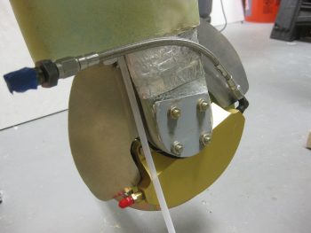
I then reassembled the left side brake assembly. I torqued all the bolts to the proper specs as outlined by Matco. I also torqued the right-side brake assembly bolts as well, but something wasn’t right and I ended up dismantling & remounting the entire right side brake assembly again. The second time was a charm and the brake disc aligned correctly between the pads & I was able to get the bolts torqued to the correct values.
Although I didn’t get a shot of the wheels, I then remounted the wheel/tire assemblies with their freshly packed bearings. I then went upstairs to review my notes on wheel pants, only to find a discussion from Bernie Siu on how each time he modified the inboard wheel pant mount assembly, he had to totally dismantle the wheel assemblies TO GET TO THE AXLE BOLT HEADS TO REMOVE THE INBOARD NUTS to swap the inboard wheel pant mount…. Doh! I guess this won’t be the last time I mount those wheels, eh?!
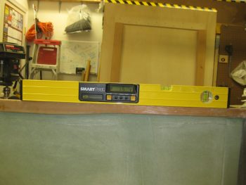
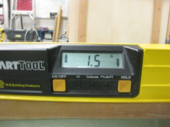
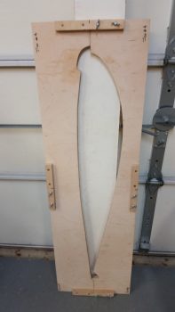
Regardless, I pressed forward with rigging the fuselage in a 1.5° nose up attitude to facilitate making the cardboard silhouettes called out for in the wheel pant installation instructions to mount the wheel pants.
With the fuselage set at the correct nose up attitude, I then set out to do what I had planned on doing yesterday: building the sawhorses to which to mount the wings & CS spar on, in turn to allow me to mount the former to the latter!
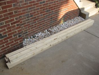
I dialed in the heights and lengths on the sawhorses and begin cutting the 2×4 lumber. Below is a shot of the respective top boards for all the sawhorses.
I got all the tops & top cross pieces cut, but when it came to the legs I was only able to squeak out 9 legs, out of the required 20 . . . Yikes! I decided to go ahead and build the first 2 sawhorses and then make a run to pick up more lumber. Instead of using screws to put these sawhorses together, I decided to go the faster route and pulled out my mojamma framing nailer.
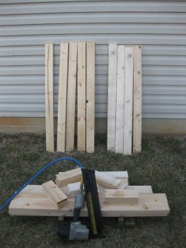
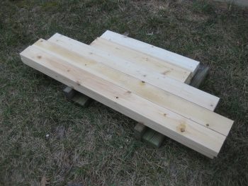
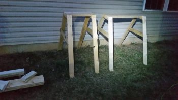
It took less than 20 min and I whipped up these babies. The narrower sawhorse to the left is for the outboard wing and the one on the right is to support the main body of the CS spar. Ok, 2 down and 3 to go! By the way, I should note that I shamelessly stole the design for these sawhorses from my buddy Mike Beasley.
It was actually a pretty good thing that I decided to cut the legs for the middle CS spar sawhorse and the 2 outboard wing sawhorses first. Why? Well, when drawing up my plan for these sawhorses, I was mentally going off of what Wayne Hicks and Mike Beasley did when they mounted their wings to the CS spar. They both pulled out their TWO wing jig #4’s and used them, one on each wing. Then it hit me (a few DOH moments today!), I only have ONE wing jig #4! And I don’t plan on making another one…
You see, I had accounted for the distance between the bottom of the wing jig and bottom of the wing and was going to subtract this from the height of these 2 inboard sawhorses when I had my mini-epiphany. I’m just thankful I caught it before making 2 sawhorses that were too short (obviously too tall would have been workable).
I packed up all my saws, tools & gear and put them in the garage before heading out to get more 2x4s. Upon my return to the house, I unloaded the lumber and then got to work sanding the mating surfaces of the wheel pants. I worked on both sides of one wheel pant for nearly an hour, and it did go back together easier . . . somewhat.
I then started on the aft end of the second wheel pant. The flange on the aft side pant isn’t too terrible difficult to sand, but the inside edge of the front side wheel pant is a bit more challenging. After nearly 1-1/2 hours of straight sanding, I decided to punt and use the Dremel Tool tomorrow on the front side.
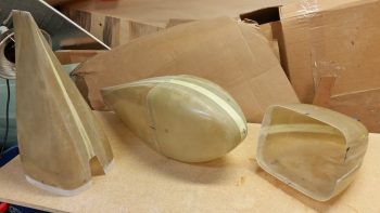
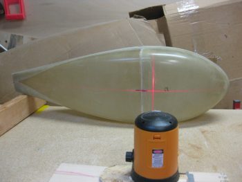
On the wheel pant that I did fully sand, I followed Bernie Siu’s method of verifying the front midpoint meets the aft midpoint meets the side midpoint. In other words, I set out to ensure that the midpoint waterline was straight horizontally all the way across my wheel pant… which it wasn’t. The nose was about 0.5″ high, so I had to work the wheel pant back and forth to get the nose down so that all the lines matched up with less than a 0.1″ discrepancy (these are naturally odd shaped wheel pants that are not symmetrical…I’ll take less than 0.1″ any day!).
To reiterate, I plan on working on the wheel pants as far as I can in the plans without actually installing them. Again, I want to have as much wheel pant “money” in the “bank” for later on so that I’m not spending a lot of time on these after I have the bird flying. It also gives me something to do during quiet hours when I’m not making loud noises prepping for the wing install.
I won’t be getting a lot done tomorrow, since my social duties are beckoning me! But I do plan on getting quite a bit done on Saturday. If everything works out right, I should be starting on mounting the wings to the CS Spar early next week!