
I started off today doing some final research on the threaded axle caps (p/n VA-106) from VANs Aircraft that makes installing Sam James’ wheel pants to Matco wheel assemblies doable without having to drill & tap the end of the Matco axles. After speaking with the guys at VANs & confirming that I had the correct part, I ordered a set.
Down in the shop I started by torquing the main gear mounting bolts (AN6-80A) to 275 in/lb as outlined in CP 46. For added strength I also added a couple drops of red Locktite to each bolt.
I then spent over an hour leveling the fuselage and ensuring it was square & plumb. As I started this process, the fuselage was really off as I tried to level it from side to side. I finally did some investigating and looked inside the overturned fuselage. It was then that I realized that the fuselage had slipped off on one side of the 2×6 sized board that I had it resting upon. Once I corrected that little SNAFU, it made the process of leveling the fuselage much easier.
In addition to shimmying the fuselage to get it level, I also used the threaded rod leveling feet that I had mounted in each corner of the fuselage dolly for the first time. They’re a bit narrow in diameter, but they definitely help.
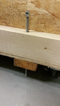
Here’s another shot.
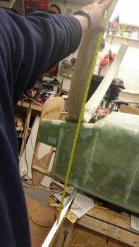
Once I ensured that the fuselage was level, I measured the distance between the main gear legs and points on the forward gear strut & the forward nose centerline.
I took 3 measurements from each gear leg, then shot 6 measurements to each leg from 2 different forward points on the nose & nose gear leg, respectively. In the end, I had 9 measurements for each leg, 3 for each specific point. I averaged each set of 3 numbers, determined the delta between the left & right gear for each set of numbers, then averaged those final deltas to get a final averaged aggregate delta.
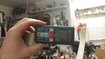
When I originally mounted the gear I had determined that one side of the main gear was a 1/4″ farther aft than the other. However, I was using a standard measuring tape when I originally mounted the gear. When I used the laser measuring device this time, my delta between the left & right side gear legs came out to only 0.087″, which is fantastic as far as I’m concerned.
After I determined that the gear legs were a close match in both elevation (I checked when I leveled the fuselage by placing a long level across the gear leg bottom edges) and forward & aft, I then determined the WL of the center of the axles.
Since the longerons sit at WL 23.0, and the axle centers are at WL -22.0, then it stands to reason that by simply measuring 45 inches from the top of the longerons to the lower gear legs that I could determine the axle mounting location. Now, there does need to be an adjustment as Marco points out on his blog since LPC#45 moves the 3/8″ bolt holes on the main landing gear mount extrusions up 0.4″, which isn’t accounted for in the WL -22.0 dimension. Thus, this moving the bolt holes up 0.4″ makes the new height of the gear at WL -21.6.
So when I measured the height of the center of the gear axle, I subtracted the 0.4″ to make the dimension 44.6″ up from the longeron (when the fuselage is upside down) to the center of the gear axle location.
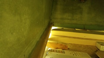
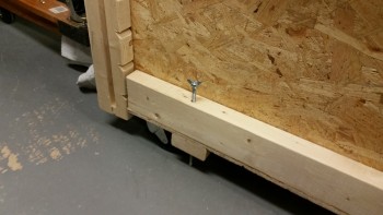
Here’s a shot of the approximate center point of the axle at 44.6″ below the longeron (at WL -21.6).
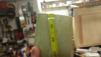
When I marked the left side gear leg, the 44.6″ mark was 1.3″ away from the end of the center of the gear leg. I really wanted another 0.2″ inches, and then lo & behold I realized that the other side of the level pressed against the longerons had slipped a bit. Once I wedged the level back tight against the longerons, I remeasured the left side and was able to reclaim my 0.2″ so that the 44.6″ mark was at 1.5″ above the bottom of the gear leg (below with the gear upside down).

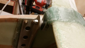
I wanted the 1.5″ gap between the bottom of the gear leg and the center point of the axle since the axle bases, as shown below, are 2″ square. Since a half inch provides room to remove some of the lower gear leg for clearance for the Matco brake calipers.
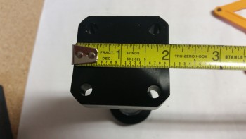
Here’s the 1/2″ mark on the left gear leg.
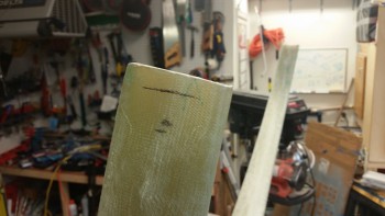
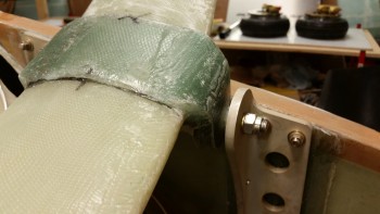
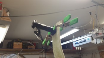
Below are the Matco axles clamped into place to test the fit, both on the left & right gear leg.
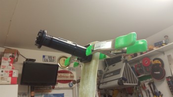
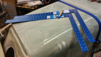
In preparation for mounting the axles to the gear legs, I made a run to Home Depot today and picked up some aluminum squares and a plumb bob, as you can see in the pic below.
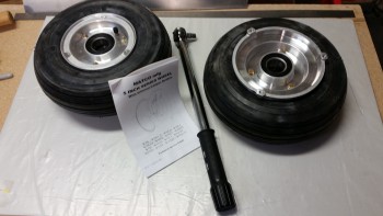
I then went back to work on the main gear wheels. The first thing I needed to do was torque all the bolts to ~99 in/lbs (8.5 ft/lbs).
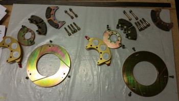
I then disassembled the brake assemblies in order to isolate the brake disk mounting flange that I will need to mount the wheel assemblies onto the axles.
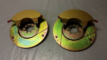
I first removed the 2 longer bolts from the outside edges of the calipers.
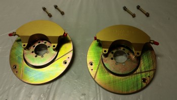
I then removed the 4 large diameter bolts in the center of the caliper assembly, and laid out all the parts as a sort of inventory & acquaintance of the parts, but specifically to ensure the brake pads looked ok & weren’t cracked (which happened to my buddy Marco).
Tomorrow I plan to mount a few 2x4s to the fuselage dolly as a quick frame to help assist in measuring the toe-in for each wheel. I’ll also be determining and aligning the wheel assemblies to the fuselage centerline. Within the next few days I plan on having the wheel assemblies installed on the lower gear legs.