
I started today by doing some more research and analysis on the steps to install the axles to the main gear legs. It’s interesting because just about every builder I know installed the axles and determined the toe-in angle close to the method described in the original plans, but to a builder they all did something significantly different than the way the plans detail the process.
Although I’m not casting doubt on the plans method entirely, I do want to optimize the process for installing the axles to the main gear & also in dialing in the toe-in angle, so some non-plans steps are most likely in order. Admittedly, since I haven’t finalized the final flow of how the axle install process, I’ll knock out all the prerequisite steps and let the process reveal itself (said while sitting in meditation position . . . ha!).
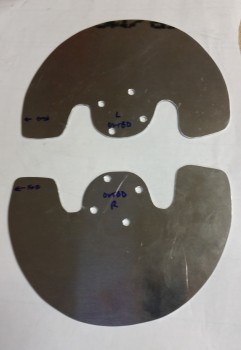
In the shop I started by spending about 45 minutes filing the edges of the heat shields to finalize their shape and remove any heinous, finger-shredding burrs (see heat shields below).
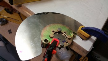
I then determined the position of the left axle on the gear strut that allowed for the optimized placement of the brake caliper to minimize the removal of the bottom gear strut material.
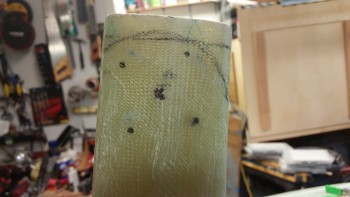
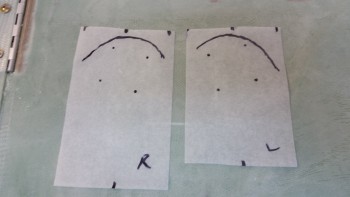
After setting the angle & position of the axle on the left side, I made up a template using tracing paper. I then transferred the mirrored image of the left side axle placement onto the right lower gear leg. Once I finalized and confirmed the placement of the axle on the right gear leg, I then made up a template for the right side as well.
These will be used IF I decide to follow the plans method which says to sand down the lower outboard gear leg to dial in the toe-in angle before trimming the gear leg or mounting the axle. Clearly if I sand the lower gear leg, all my markings that I just finalized will be wiped out. Thus, with my templates I can reapply my markings after shaping the gear legs for the toe-in.
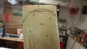
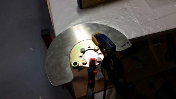
Here’s the right side lower gear with both the axle placement and lower gear removal markings shown.
Once I finalized the positioning of the axle, I used the wheel mounting flange as a template to drill the 1/4″ mounting holes in the left heat shield.
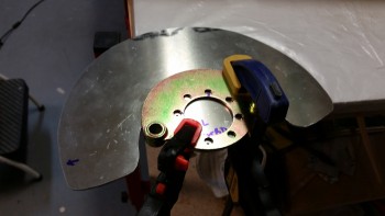
Here’s the left heat shield mounting bolt holes drilled with the test fitting AN4 bolts installed.
And here’s the right heat shield mounting holes drilled.
A shot of both heat shields with the holes deburred & the sides filed smooth.
After finishing with the heat shields, I started work to attach the aluminum squares to the axles to determine wheel toe-in. I wrapped the axles with tape to protect them from any out of control glue gunk. I also used a zip tie to keep the square tight against the axle.
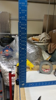
I then used the free square to ensure that the first square I was gluing to the axle was …. yep, square.
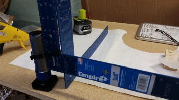
I then glued the second square to the other axle.
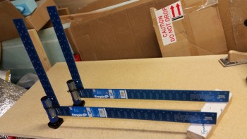
Tomorrow I’ll borrow a page out my buddy Marco’s book and build a smaller version of his “Straight Tower of Pisa” to track the fuselage CL and dial in the toe-ins for each wheel assembly. After I get the tower built, I’ll start the steps to mount the axles to the gear legs.