
We’ve had stormy weather all along the Atlantic Coast, and even as far inland as Tennessee… where sadly a couple of airports got hit pretty hard. This of course makes it difficult to pull all my saws outside to cut wood and foam, without everything getting drenched. What’s worse is that it’s been a bit sporadic, so I’ve had some false starts where I get set up, a few things cut and then come the downpours! …. ugh.
Part of getting the workshop up to speed is to get all the respective capabilities up to speed as well. I have a fair amount of machining and lathe work to do on a bunch of components to finish up the plane. I’m new to machining, and CNC, so there is a steep learning curve that I’m trying to stay out in front of as best possible to get this stuff up and running as soon as the shop is work ready.
As I noted a few days ago, I 3D-printed some PETG parts for the spindle encoder installation on the lathe. This will be an integral part of allowing the Acorn CNC software to control both the speed (RPMs) and direction of the lathe.
Well, with the weather acting as it is today was perfect to engage in indoor activities. So I dusted off my epoxy skills and mixed a few grams of epoxy to then further whip into some wet flox. I used the flox to mount the 45-tooth gear (bottom gear in pic below) and slathered it on to ensure my stringy (fairly normal) PETG encoder spindle-to-gear attachment nub was as strong as possible.
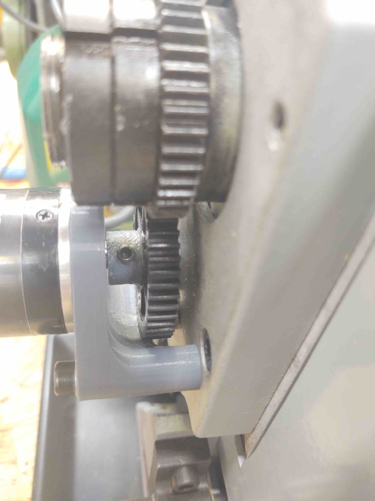
One common issue with adding these spindle encoders to smaller hobby lathes is that once installed, the left side lathe gear & spindle cover can’t be remounted without some modification.
The modification is quite simple actually and only requires drilling a hole a bit bigger than the spindle encoder so it can peek through the cover. Depending on the configuration, the spindle encoder cable exiting the side of the spindle encoder must be contended with… as was the case with my install.
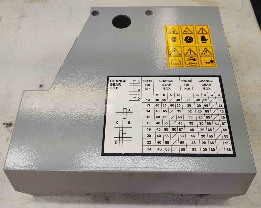
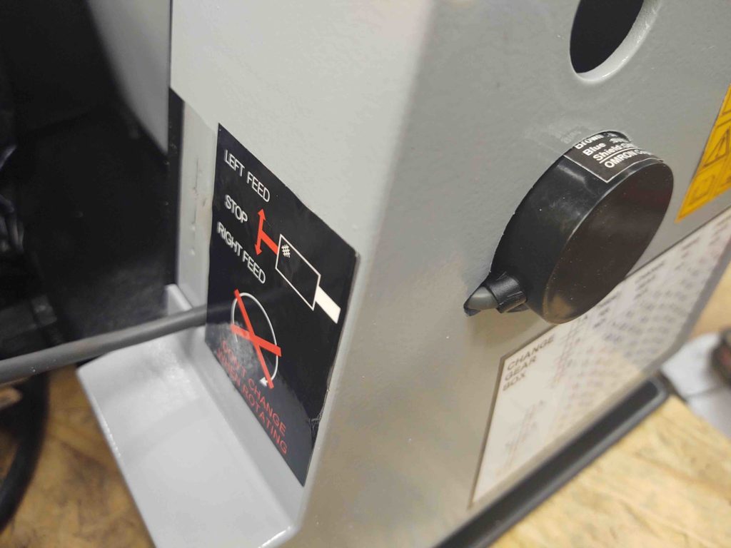
Here is the unmodified left side lathe cover [Note the bottom sticker regarding manual gear switching for threading ops will no longer be needed when CNC is used].
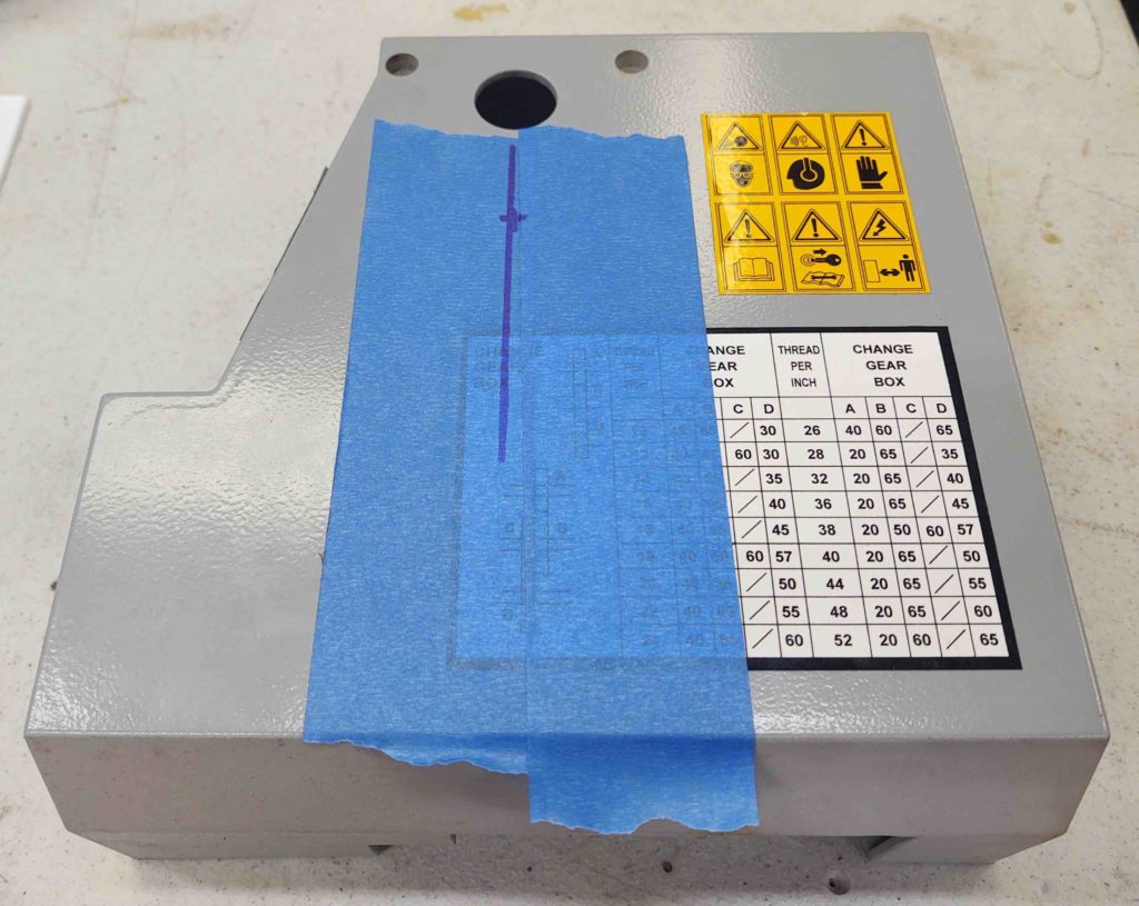
I applied some blue painters’ tape to protect the cover and the hole. I then measured and make my bullseye mark for drilling.
I was very pleased with the way the hole came out, although I was aiming for a certain position to optimize clearance for the cable that I just didn’t quite get.
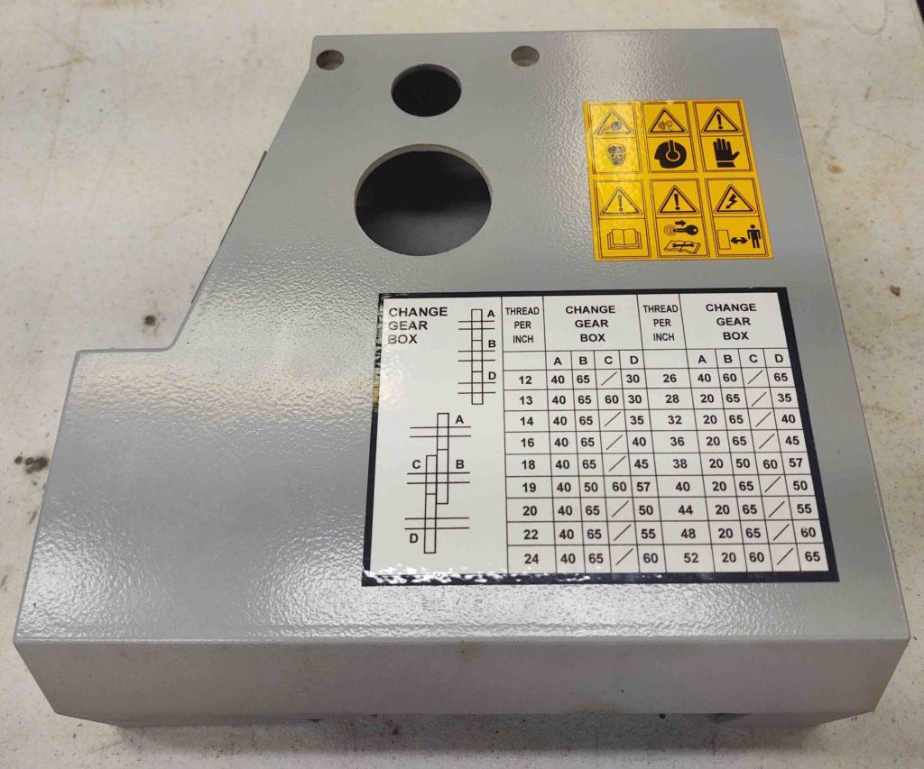
I wanted the area of the hole closest to the spindle encoder to be around the 2 O’Clock position while the area farthest from the spindle encoder (aka the biggest gap) to be around the 7-8 O’Clock position. Again, to allow the best clearance possible for the cable.
As you can see below, my hole ended up being offset straight up and down: closest at the 12 position and farthest at the 6 position… which is much better than the opposite.
BTW, I used a 1-3/4″ hole saw to make the spindle encoder hole.

Here you can see that I had to make another little notch off the big hole with the Dremel Tool to allow the cover to be reattached without pinching the spindle encoder cable.
One more thing I did that I didn’t get a shot of was trimming the individual wires at the far end of the spindle encoder cable and crimping on D-Sub connector pins.
Overall I’m very happy with this install. It came out nice and clean and the configuration looks like it should work well.