
Chapter 23 – Engine Dehydrator
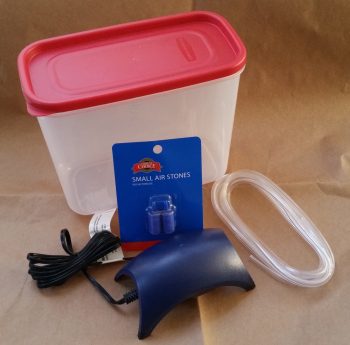
1 February 2018 — In prep for the engine coming home to my shop, I slowly bought all the parts I need for my engine dehydrator ala Bill Allen’s FaceBook post where he provides details on how to construct one of these things for fairly cheap (see video below). Here are the components I’ve acquired. In addition, I also ordered 4 each cylinder dehydrator plugs from ACS. I figure between an active airflow dehydrator and the cylinder plugs, it should keep the engine internals quite dry enough to prevent galling or corrosion. Moreover, I don’t want to do a full on oil-soaked pickling of the engine since I really think it will only be unused for less than a year at the very most.
Bill Allen’s engine dehumidifier video:
•••
5 February 2018 — Today I continued to prep for the eventual engine storage in my shop.
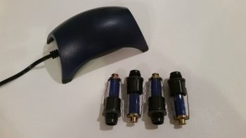
With the engine being a brand new build, it is more susceptible to internal corrosion than a broken in/mid-time engine and requires some prophylactic measures to ensure it remains corrosion and gall free…. as Bill Allen points out in his video on his engine dehumidifier that I included in my last post. Bellow are pictured the 2 primary methods I will employ to help guard against any internal moisture within the engine: A) an active airflow engine dehumidifier (dehydrator) using a small aquarium air pump at the heart of the system, and B) passive cylinder dehydrator plugs that are mounted in the spark plug holes … just one per cylinder.
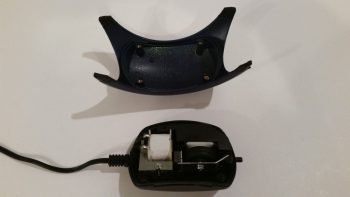
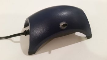
For the engine dehydrator system, a couple slight modifications are required. So I removed the 4 small screws to pop the top cover off.
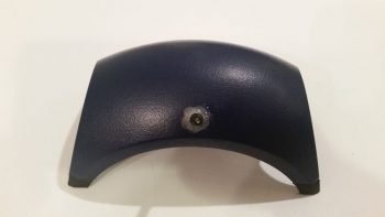
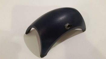
And then drilled a small hole at the center point, near the side edge of the cover.
There was a “T” fitting included with the pump, and since it was the correct diameter for the tubing I would be using, I cut one side of it off to press into service as an air hose barb to turn the small hole I drilled above into an air intake hole.
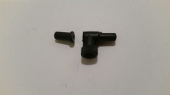
I then used the small drill bit that I used to drill the hole to align the inlet barb with the hole. I then used some 5-min glue to secure the barb to the side of the air pump cover.
Voila! I now have an air intake barb on the side of my air pump. This will allow the pump to drive air out of the standard outlet that is configured on this pump, and now simultaneously draw air back into the pump through this air intake. This turns a standard OUT-only pump which uses outside air for a fish tank to be transformed into a closed air pump system.
This shot is to show the daylight that can be seen from the inside with the air inlet barb glued in place on the external surface of the air pump top cover.
I then reattached the air pump’s top cover and secured it with the 4 screws.
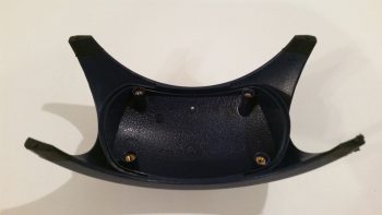
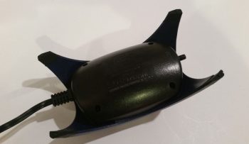
The second and final step required for this modification to transform this pump into a closed system is to tape off the filtered air inlet valve on the bottom of the pump (which somewhat resembles a small upturned decapitated rodent in this pic…)
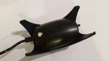
With the application of just a small piece of electrical tape, my out-only air pump has now been transformed into a closed-loop air pump/vacuum (albeit the “vacuum” force created is exceedingly small… this is simply more just an air return inlet).
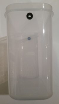
On the engine dehydrator system’s desiccant container I then drilled a 3/8″ hole at the top on each side for the tubing to be run through. I then placed a rubber grommet into each hole.
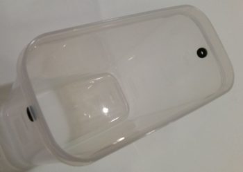
Here’s an end shot of the rubber-grommeted holes on the sides of the engine dehydrator’s desiccant container.
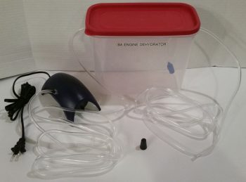
And here’s a shot of the entire engine dehydrator system as it looks so far. Once the humidity meters and desiccant that I ordered arrive I’ll have all the parts on hand. I would like to especially thank Bill Allen and “Drummer” Dan for providing the specific details via FaceBook on how to construct this engine dehydrator.
•••
22 February 2018 — When I checked my mail today, lo & behold, the long lost humidity sensors/ meters for my engine dehydrator system finally arrived. They’re a bit off in temp reading –which I don’t really care about– but in the house they are spot-on regarding their humidity readings. As you can also see by the 9V battery that I included for size reference, these meters are quite small.
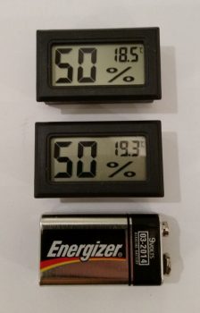
I checked the weather online and saw that the humidity was rated at 88% at Mount Vernon, a few miles from here. So, I took my humidity meters out on the deck and left them there for a good hour before remembering that they were out there. I snapped this pic an hour after the 88% report and again, a few miles away from the reported site (not expecting them to be exact either). These are fairly close and really in line with what I read about these meters (in that with high and low extremes they may stray more from the actual humidity vs midrange where the reading tends to be closer to actual).
Regardless, they’ll definitely do for what I need in my engine dehydrator. Good stuff!

•••
2 March 2018 — Today I was able to grab the parts I needed to finish off the Engine Dehydrator System. So, as I often do, I made a video to provide an overview of this system.
•••
18 March 2018 — Today I took a hard look at my engine preservation steps. I’m not exactly sure what’s going on with my engine dehydrator. It’s definitely doing something because the “dilithium” crystals (desiccant) are turning pink, but the humidity sensor on my out air line keeps showing an internal relative humidity only about 5% less than ambient in the shop. An example for clarity, say the shop RH is 37%, than the air out of engine will be around 32-34%. Maybe the 40 gal fish tank air pump I’m using is not big enough and I need more air getting pushed through? Or the fact that this engine has gaping holes (albeit taped up) in it since it’s not all put together? Not sure.
I did rewicker the dry air to enter the engine via the oil filler neck and out the crankcase vent vs. the other way around. Also, I disconnected the out line that was going back into the air pump and instead of a closed system I’m trying a simple dry air in and then wetter air out to shop air. I’ll assess if this has any impact on reducing the internal moisture in the engine.
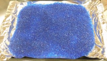
I then tried my hand at baking all the pink desiccant I had collected in a small plastic tub. I put it all on aluminum foil on a baking pan, fired up the oven to 240° F and cooked them for about 1.5 hours.
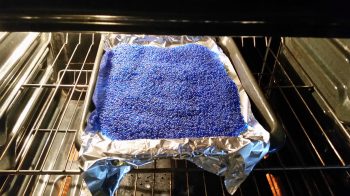
As you can see (although I guess a before pic would have been a good idea eh?) this baking thing really works and turns the quite pink desiccant crystals back to blue. It’s hard to capture the brilliant blue with a camera, but it’s a drastic difference. Pretty cool.
Although I have no doubt that my desiccant efforts is vastly helping keeping my engine internals dry-er, it doesn’t negate the fact that I need to get this engine pickled… and soon! Thus, weather be damned I’m going back into the shop.
•••
19 March 2018 — Today I was very pleased that with an ambient humidity reading of 36% in the shop . . .
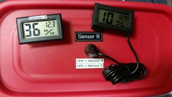
that my new engine dehydrator configuration yielded only 18% humidity internal to the engine! Now, that’s more like it! Anything under 30% is good and means minimal moisture in the engine, so obviously 18% is way better . . . that helps, but I still want to get this engine pickled soon.
•••
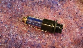
25 March 2018 — I feel like I have a cat now because I started off the day skimming the top layer of pink desiccant out of the engine dehydrator container (just like the proverbial kitty litter box). I also pulled initially 2, then 3, engine dehydrator plugs and swapped out their pinkish desiccant for nice deep, rich blue desiccant.
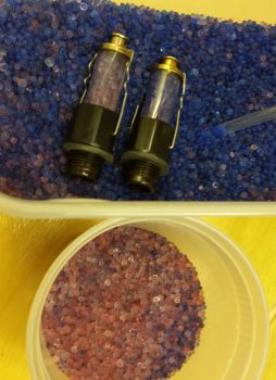
Here’s the third and last engine dehydrator plug in which I swapped the desiccant out. I placed it on the bed of pink desiccant that I was just getting ready to pop in the oven for an hour or two at 240° F. Not pictured are a half dozen desiccant bags I pulled out of the engine’s exhaust ports and air intake plenum to also dry out as well.
After the desiccant returned back to its brilliant blue color, I dumped it back into the engine dehumidifier tub and replaced all the desiccant bags. Before I did all this my engine was at 21% relative humidity internally, and about a half hour after I finished with my desiccant shenanigans it was back down to 12%.
•••
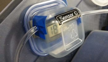
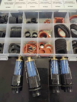
7 September 2020 — Today I took a trip downtown to Harbor Freight to pick up some ring gasket/seals (or flat O-rings) for the engine desiccant plugs. These desiccant plugs are great for soaking up the moisture in the cylinders, but their design –especially for their price– leaves a little to be desired. To keep the moisture out of the cylinder, as denoted by how long the desiccant stays blue, you need a fairly tight seal on the rubber ring gasket. The problem is a decently firm torque deforms these rubber seals out of shape in too short of time [torque too much and you’ll bust one of these off in your spark plug hole… don’t ask me how I know!].
With new seals in hand I went back home and flipped the engine back upright. I put the refreshed desiccant plugs back in the upper spark plug holes and hooked up the desiccant air dryer to the engine.
•••