
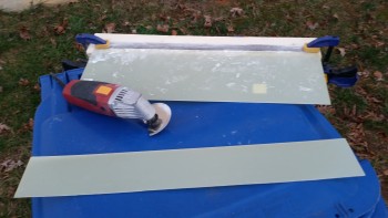
Since it was an unseasonably warm day today, I figured I had better get my glass cutting in while I can. What does cutting glass have to do with the weather? Well, I don’t like putting my bike out in the weather nor do I like opening the garage if it’s really cold outside unless I really have to. So I rolled the bike out in the driveway and then had unhindered access to the cutting table.
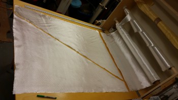
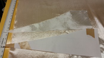
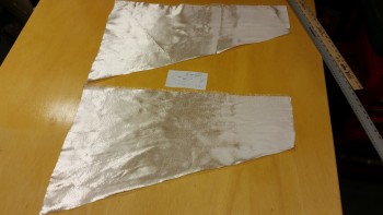
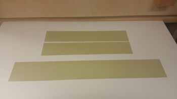
I’m using the same layup schedule as my buddy Ary Glantz used on his nose (with some additions) since per the original Long-EZ plans “fiber orientation is optional.” I cut 4 panels to cover the entire nose, 1 panel covers from the top on the side down to the bottom side nose CL. In the pic below you see 2 of these panels. They measure 44″ front to back, 33″ tall aft and 5″ tall forward. And as you can see again below, the stock width on a roll of BID is 38″, so 2 panels can be made out of a 38″ wide x 44″ long piece of BID.
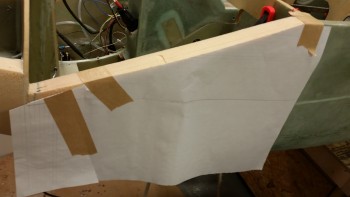
Because I sinned grievously by thinning my sidewalls on the nose, I added one extra ply on the inside, and I will add 1 extra ply on the exterior side as well. However, I am only adding the extra ply in the immediate area of the thinned panel, and not the entire nose. To ensure I got the correct cut, I made up a template of the nose side panel.
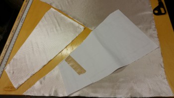
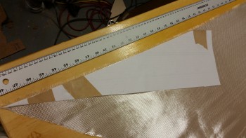
I then used my template to cut out a ply of BID for each side, only this time I did go with the 45° fiber orientation to give it a little bit extra umph! This ply of BID will not actually be the next piece of glass to get laid up on the nose after the two big side pieces above. I will also be adding a ply of UNI to each side as well, as per below.
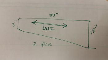
As I stated above, I’ll be adding a ply of UNI to the bottom nose layup. However, although there will only be 1 ply of UNI, there will be 2 actual pieces of UNI. The top piece per side will have the major fiber orientation parallel to the top of the nose side piece. So, in other words, angled down slightly. These fibers will essentially act as cables (as all glass does, not trying to overstate the obvious here!) securing the cantilevered nose to F22.
To get this template, I merely chopped off the top part of my previous BID template.
I was about ready to cut the first upper UNI portion off my roll of UNI when my Spidey senses told me to stop! I had almost forgot that I had a big tub of scrap UNI glass, and a lot of those pieces are fairly large.
I quickly found that I had plenty of spare UNI pieces to use other than cutting this piece off the roll.
I then measured out the requirements for my bottom UNI piece that will get glassed into place with the fiber orientation horizontal.
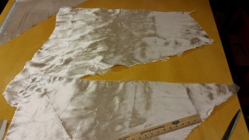
I found 2 more large pieces in my spare UNI bin so I took them out to assess them.
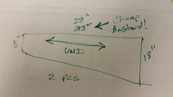
Somehow, and I’m not quite sure, my requirements for the lower UNI glass pieces changed! ha! Since the above pieces could provide me 28″ long pieces, I decided to simply shorten my measurements on my extra glass by 5″. This puts the front of the UNI ending about in the middle of the battery compartment sidewalls vs the front of the battery compartment if it had measured 33″ in length.
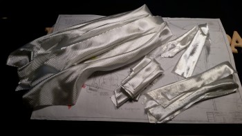
Here are the larger, lower pieces of UNI, one ply per side. I thought it was pretty cool that I didn’t use one piece of UNI off my UNI roll! This is all basically “free” glass.
Below is a shot of all the glass for the layup on the bottom of the nose. All the glass in the lower right hand corner is extra. If you’re wondering how much extra weight that will add, it weighs out at right about 0.52 lbs. Double that to get the approximate weight of the epoxy and we’re talking about a little over a pound in added weight. With the amount of added strength it provides the nose (albeit I’m not an engineer), I’ll take the weight penalty!
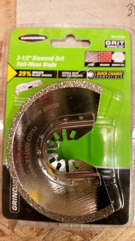
With all the nose glass cut, it was time to get one more outside task off the list. When I went to Harbor Freight last night, I was considering purchasing a wet/dry tile cutting saw with a diamond blade since that’s what my research revealed as the power tool de jour for cutting G10 according to the online forums. Well, even with the sale going on it would have been a bit pricey, at least quadruple for what I ended paying for this $11 diamond Fein saw blade. I figured I would try this out and then if it didn’t work I would go with the more expensive option.
I marked my 1/16″ piece of G10 to cut off a slab of 3.6″ wide that I’ll be using for my nose gear strut fairing.
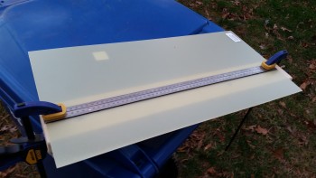
Cutting slow and using the metal measuring stick as a guide, it only took me a few minutes to cut right through this piece of G10. Certainly, if this were a 1/8″ thick piece I think it would still do it, but it wouldn’t be nearly as pleasant of experience.
I ended up cutting a couple of rough 3″ x 16″ blanks for my nose gear doors as well.
It was starting to get fairly dark when I was cutting my last G10 nose gear door, so I took my operations back into the shop. With my outside activities completed, I started back on the nose area. I trimmed the left & right corner reinforcement plates that I installed last night. I also sanded all the un-peel plied glass edges to avoid any painful “gotchas” later on down the road.
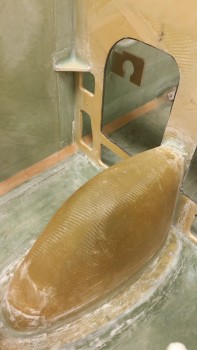
After vacuuming up the mess I made in the instrument panel area, it was time to make an even bigger mess by getting back to sanding the nose. I pulled out the long board with 36 grit sandpaper and went to town.
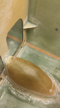
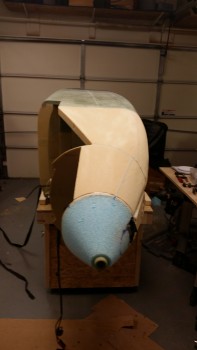
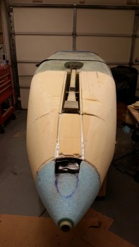
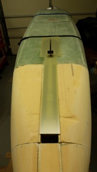
Here’s a higher-up angle shot of the nose.
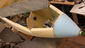
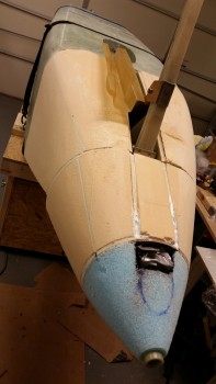
Here’s the right side of the nose. That divot towards the aft side of the foam is where I got a little too aggressive with the saw during one of my first initial cuts. I’ll remedy that of course as I glass the nose.
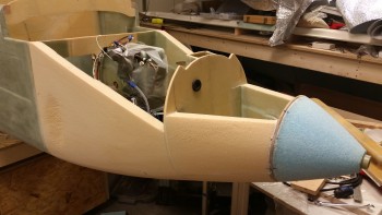
And a pic of the left side as well.
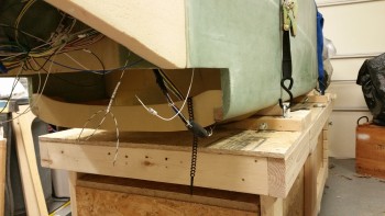
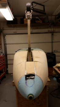
After the sanding of all the upper surfaces of the nose was complete, it was then time to flip the fuselage upside down. I started by wedging the nose of the fuselage higher so I could remove the forward fuselage dolly saddle.
I then did the same in the back, and here’s the result:
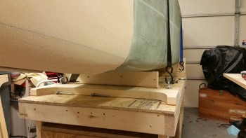
I loosened the tie down straps and slowly flipped the fuselage over onto its side.
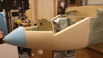
Here’s a requisite nose shot with the fuselage on its side.
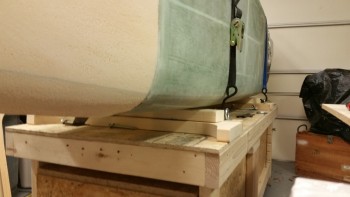
And then finally flipped it completely upside down.
It’s amazing how big this bird looks now! That nose really adds a lot of area!
A view from aft.
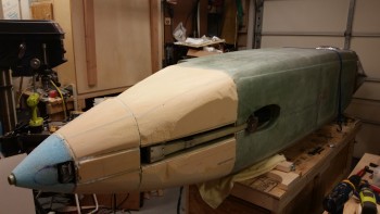
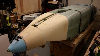
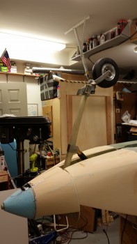
And a couple straight on shots, nose gear up & down.
A side shot with the nose gear extended.
I plan on getting the prefab nose gear cover (SC) installed tomorrow.
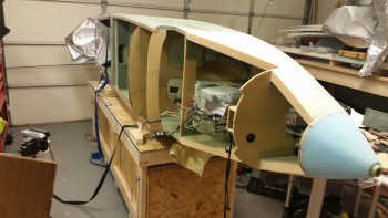
And here’s one last shot with the G10 nose gear strut fairing and gear doors mocked up. Can’t wait until those are on!
Tomorrow will be a busy day. Like I said, I plan on getting the gear strut cover (SC) installed. Before I can do that though I need to glass the underside forward NG30 cover nutplate assemblies, draft plate, etc. I may need to increase the height of the SC as well just as I did the nose wheel box (NB). As you can see, it will be at least one more day before I actually get to glassing the nose, which now I’m thinking will be Tuesday, but may be as late as Wednesday or Thursday. Much to do, much to do!