
I started off this morning working for about an hour on some build project housecleaning duties such as updating my spreadsheet with recent purchases, and my project “Order of Battle,” and my specific to-do lists for each chapter.
After getting the paperwork out of the way, my first priority of the day was to work on all the stuff that makes noise. If noise wasn’t an issue, I would have worked on the canard first, then the nose NG30’s, and then the fuselage dolly. But, since I can’t be making enemies of all my neighbors, or keeping the neighborhood awake with my plane-building shenanigans, then I need to prioritize to get my clanging & banging finished ASAP in the day.
I started off today working on the NG30’s for the nose. I needed to get some minor stuff taken care of so I could glass the aft inboard side with a 2-ply BID layup. This layup would serve 2 purposes: 1) It covers the depression made in the upper aft area of each NG30 to allow freedom of movement of the nose gear actuator housing, and 2) It reinforces the aft inboard edge of each NG30 with 2 plies of BID to strengthen the NG30 when attached to the center post of F22. This was a recommendation I received from Jack Wilhelmson back in 2012, so I of course complied!
The first of this required stuff was to drill the 1/4″ holes for the actuator mounting brackets in the right NG30, by using the left NG30 as a template to make sure the holes are perfectly aligned. Once the NG30’s were aligned and clamped it took very little time to drill the holes.

The next order of business was to expand the NG30 upper holes that provide clearance to the main nose gear actuator connect bolts. This expansion is a result of the boo-boo that I mentioned earlier where I overlooked Jack’s mandate that the holes on the edge of the actuator mounting brackets are required to have 3/8″ clearance from the edge of each bracket to the bolt hole. I’m fairly certain I was using the original holes shown in the old plans NG51s (mount for mechanical nose gear retract assembly) for reference, and those didn’t have the proper clearance. The bottom line is that since I had to move the holes on the mounting bracket further away from the edge, it caused an issue of bolt clearance in the very top open hole. It needed about 0.15″ more space at the aft end of the hole.
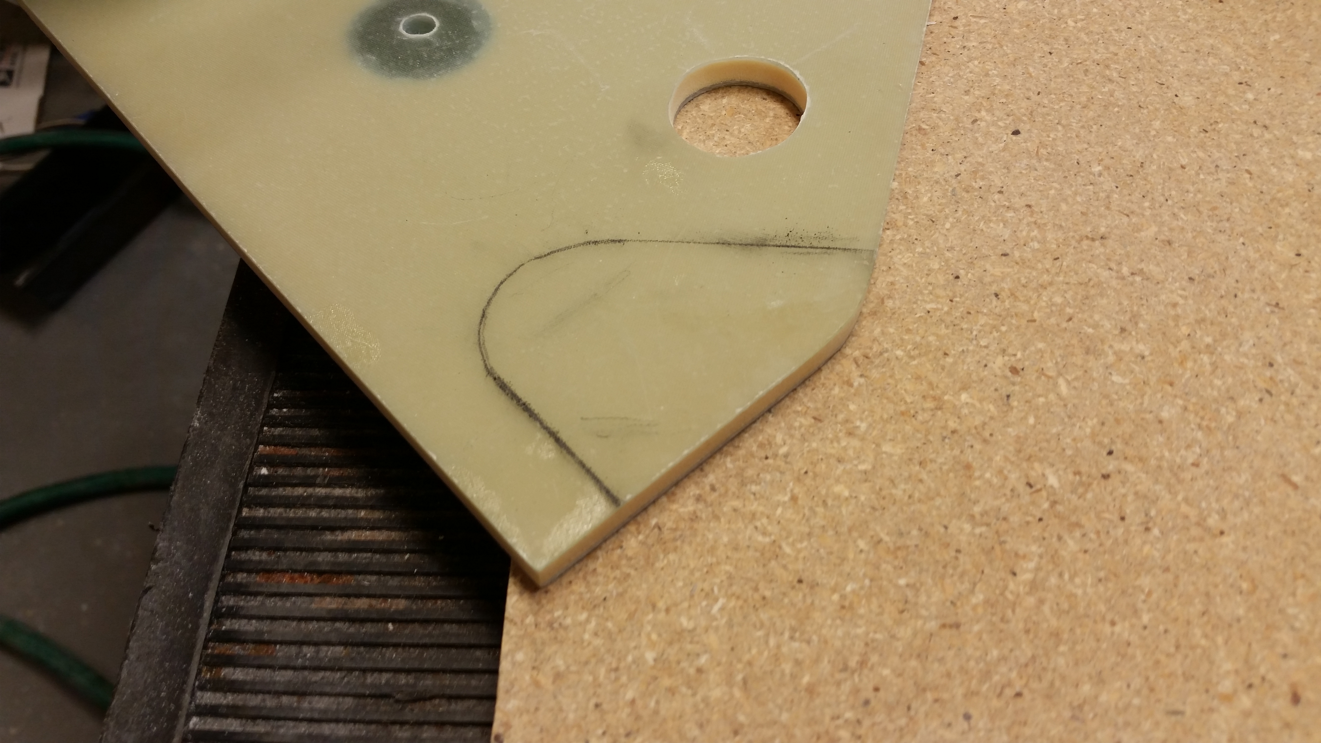
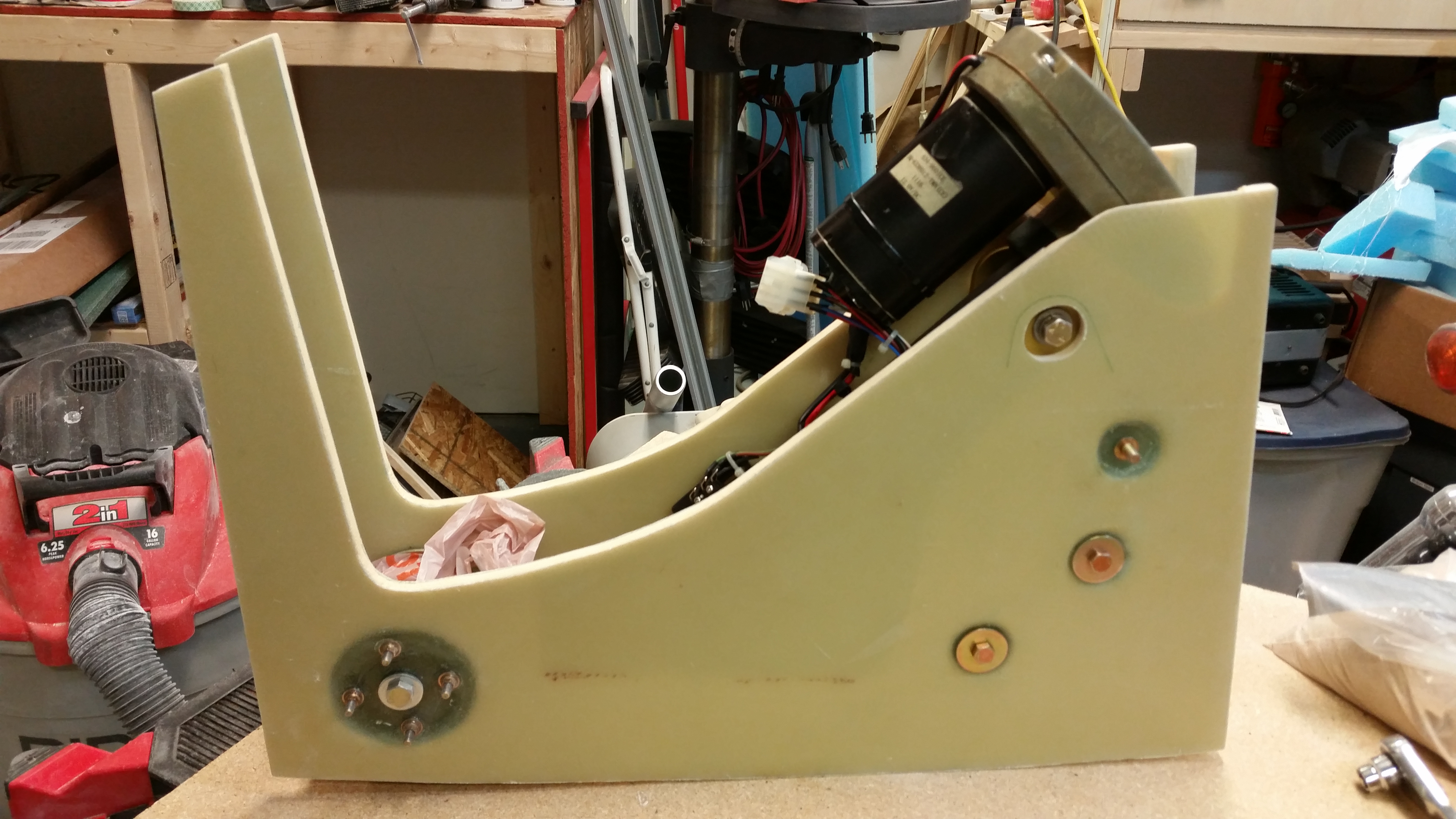
As I was checking the spacing on the upper NG30 hole below with the actuator installed (see pic below), I also marked off the area of the upper NG30 that needed to be removed to allow the proper clearance of the nose gear actuator top motor housing (the anodized gold cap at the bottom of the actuator in pic below).
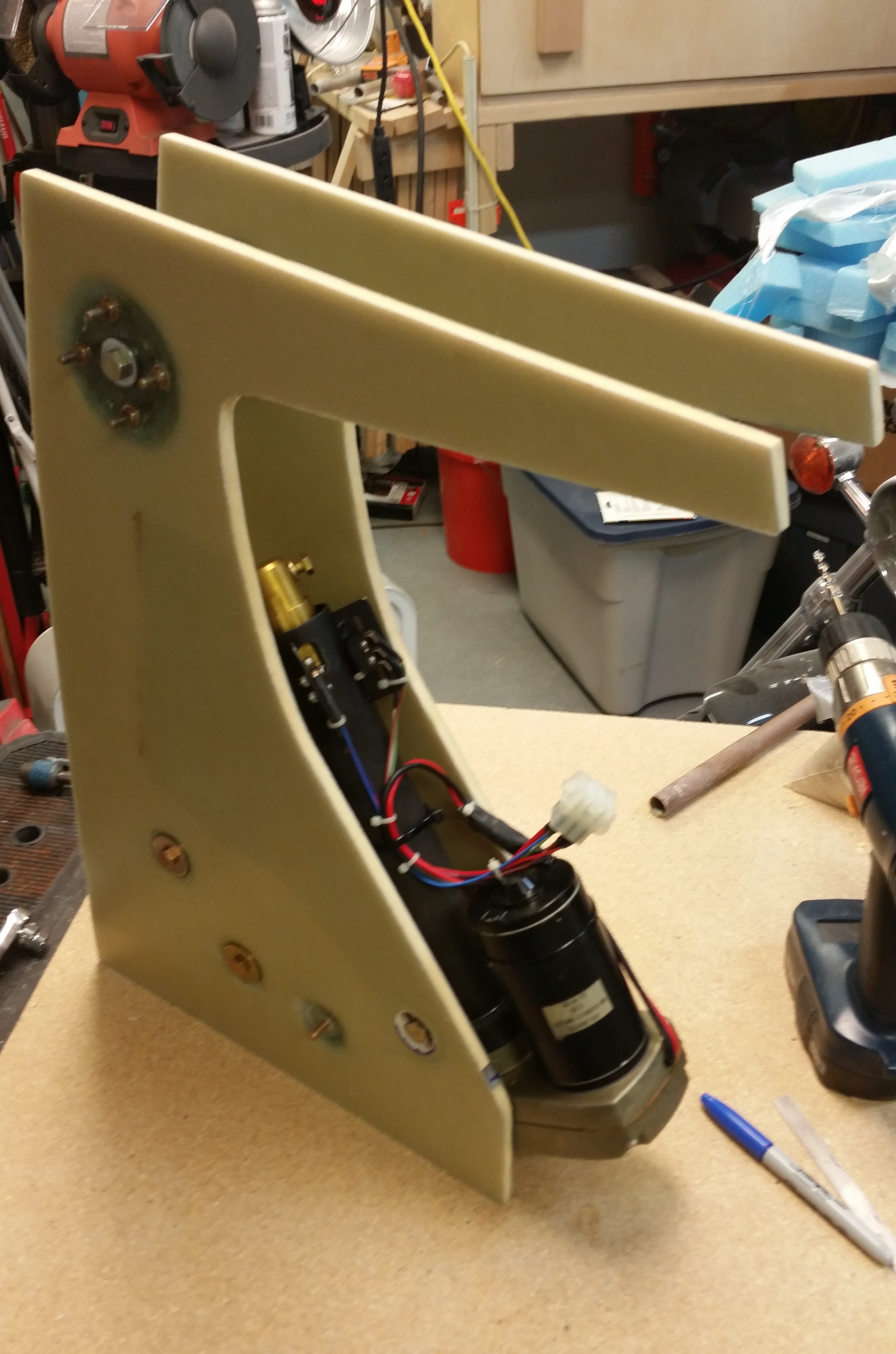
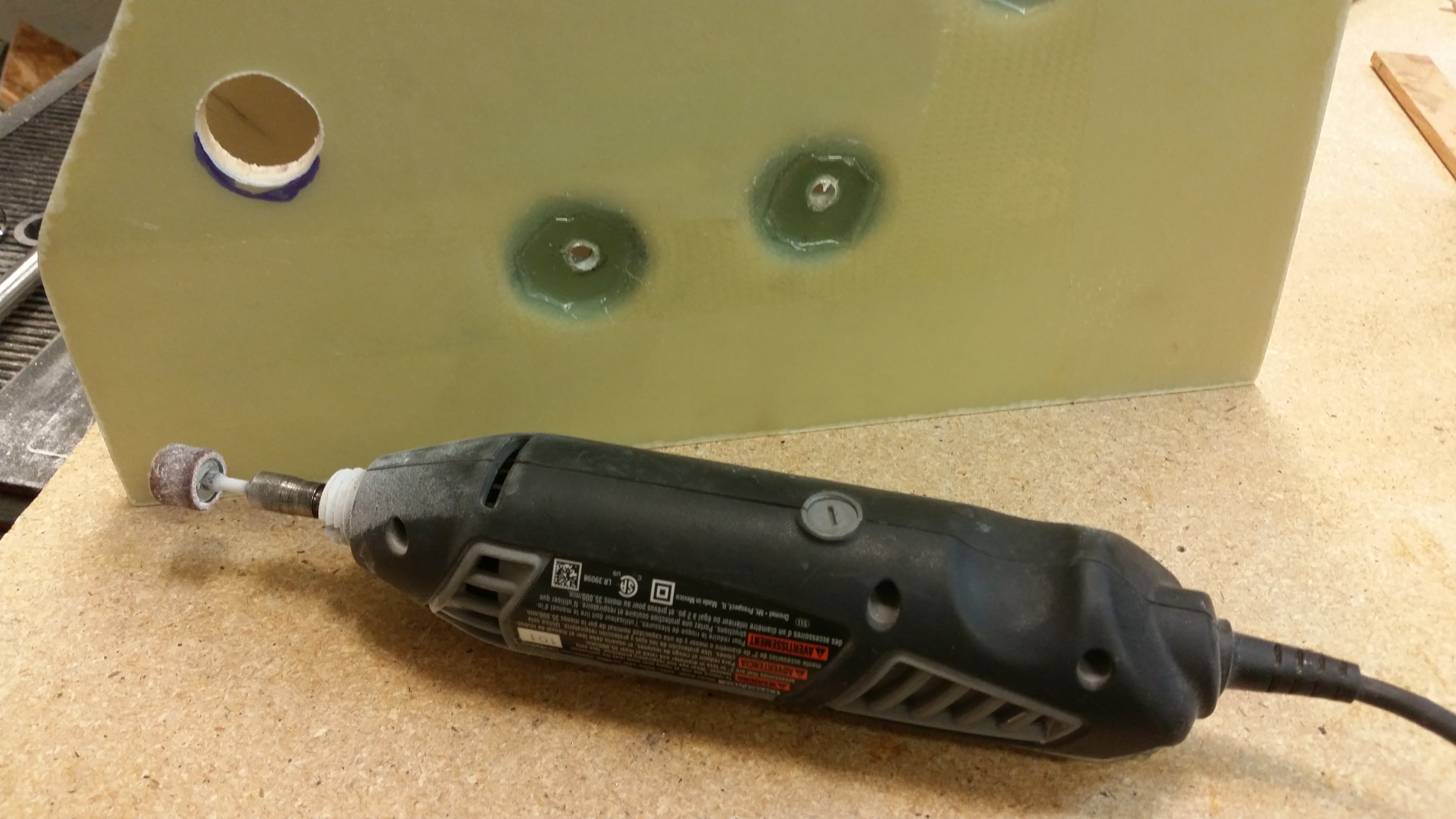
Here I’ve prepped the Dremel tool to use on expanding the upper holes. The area marked at the bottom of the hole is the offending mass that must be removed!
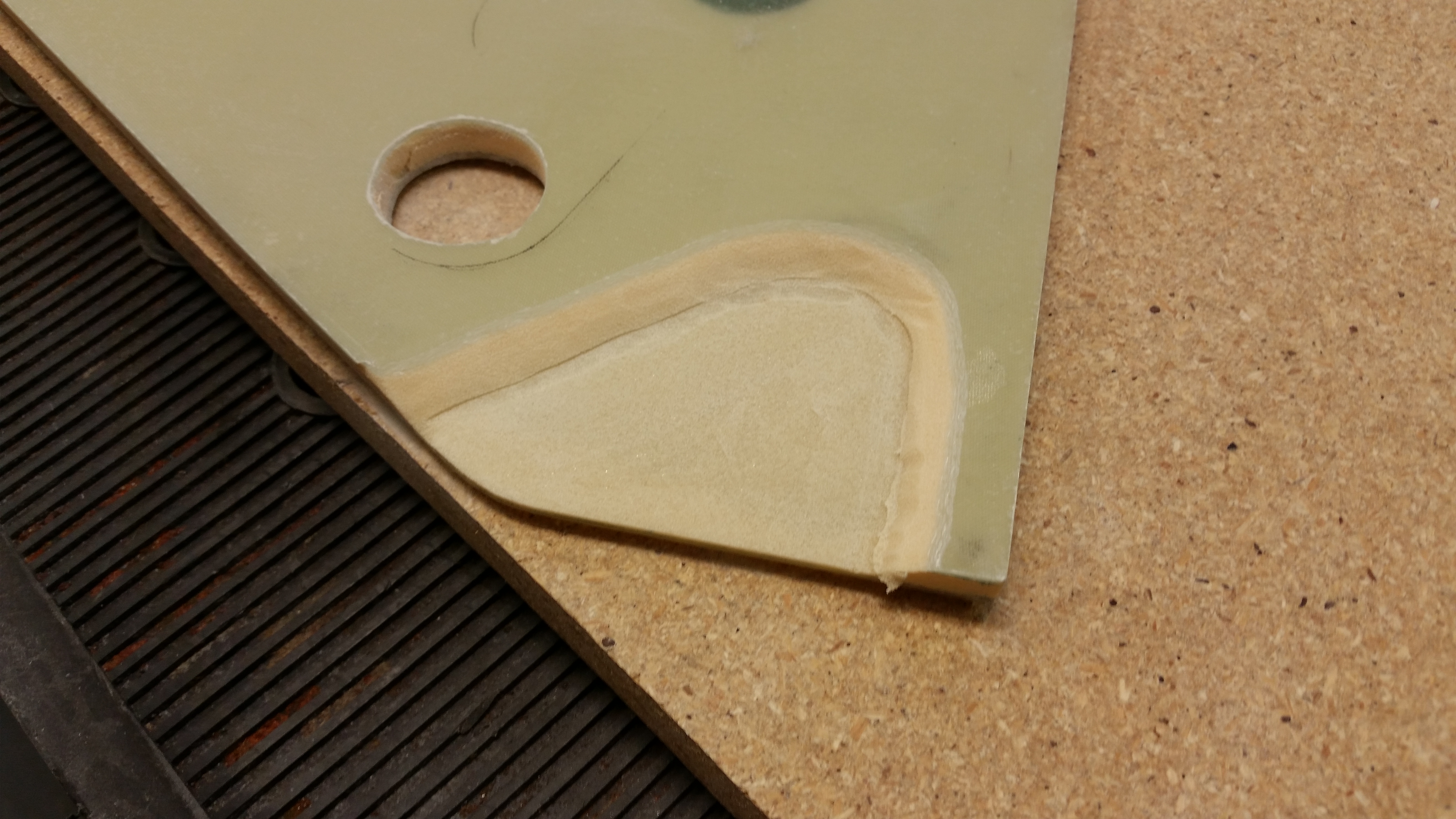
The last task on my list before glassing the inboard NG30’s was to remove the area that I had marked off above to allow unhindered movement of the nose gear actuator.
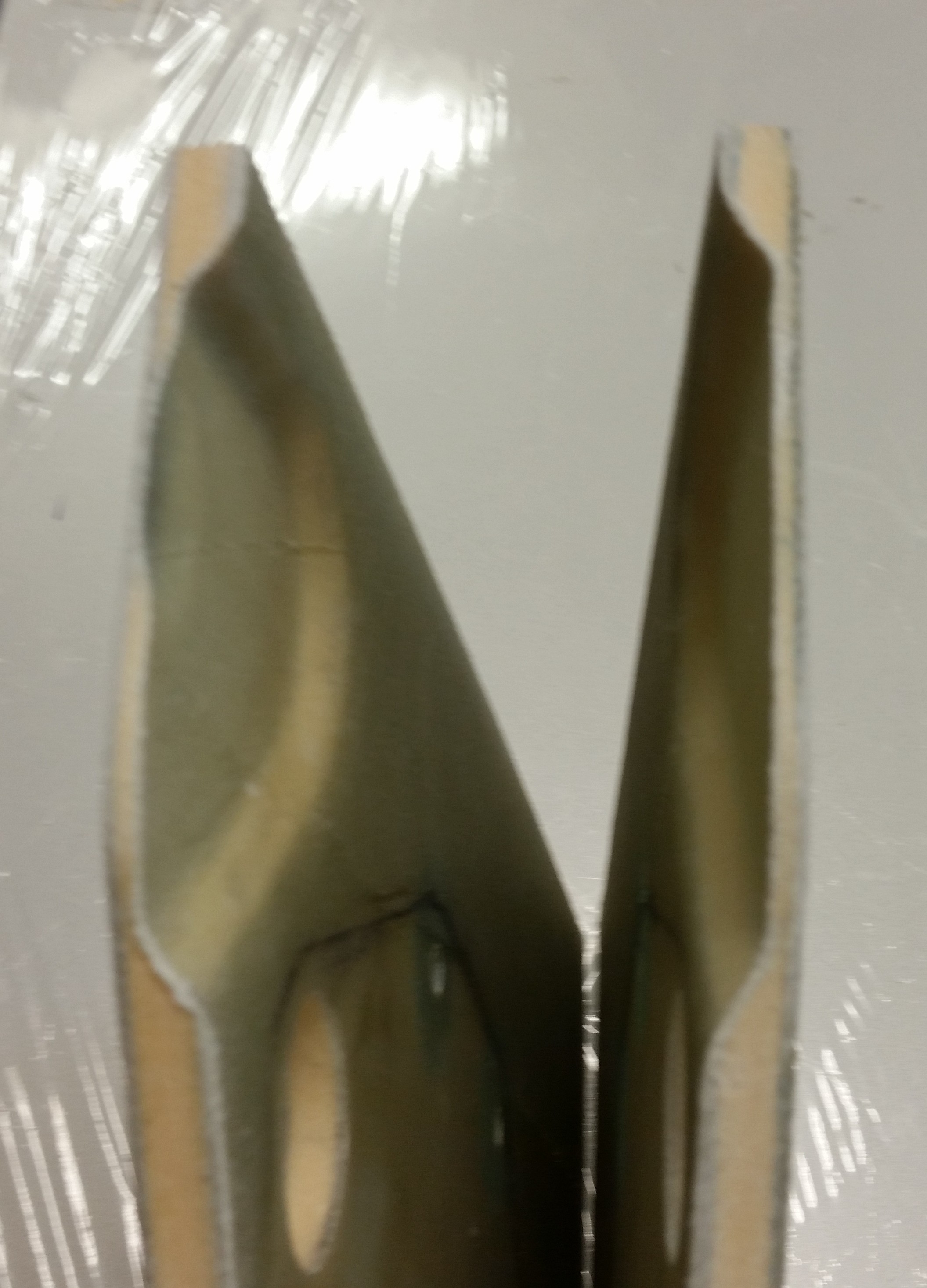
I used my router with a 3/8″ “square” bit and freehanded the cutting into the NG30 tops. I set the depth at just a hair over 0.2″ (say, 0.21″)
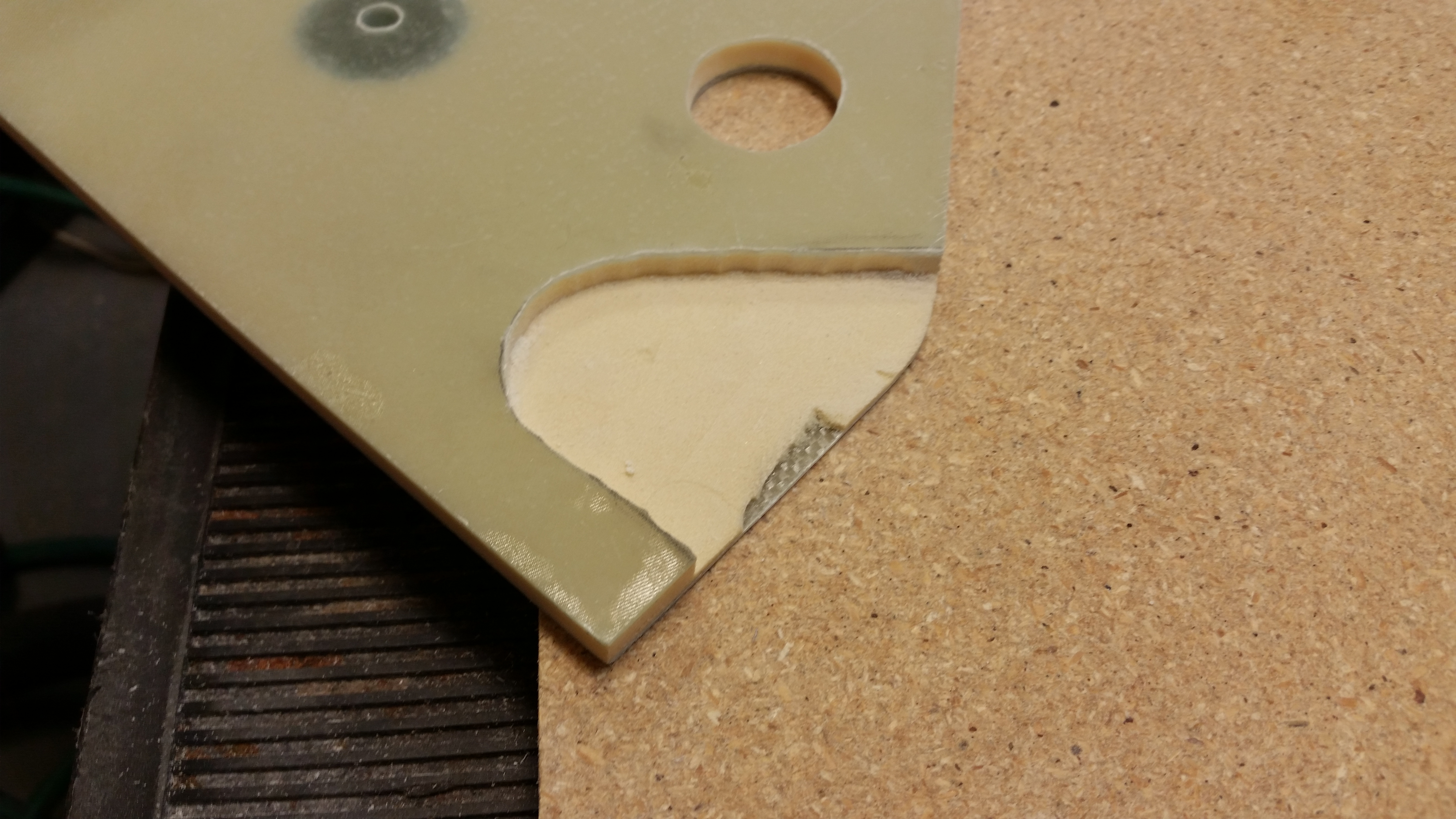
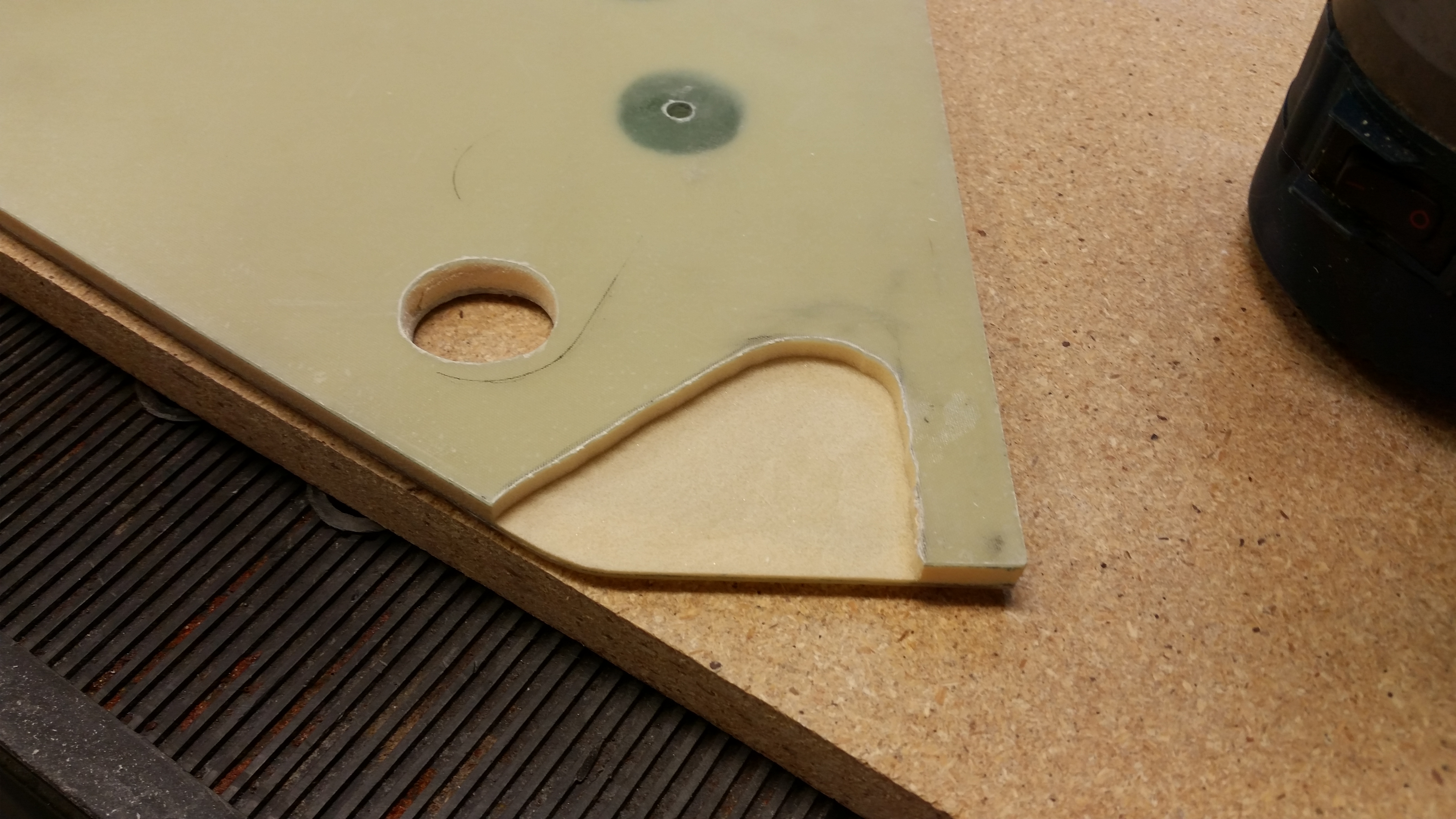
After using the straight bit, I used a “V” bit to bevel the edges of the depression.

I then set everything back up to ensure that the top of the nose gear actuator motor housing had plenty of space, which it did.
And I also checked that upper side holes provided the correct clearance for the main nose gear actuator attach bolt, which you can clearly see that it does below.

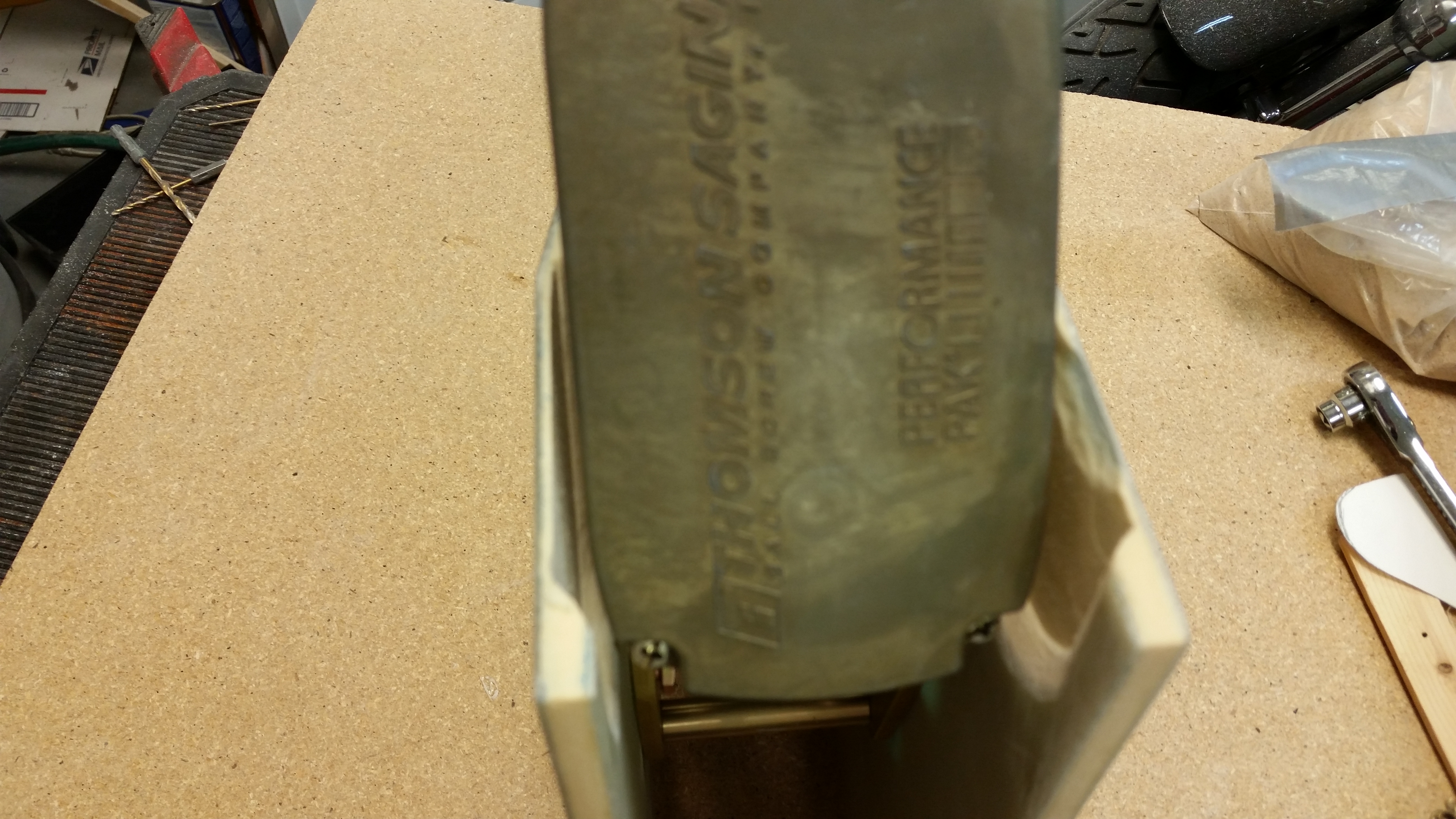
And finally, a shot from aft showing the clearance between the actuator motor housing and the sides of the NG30’s.
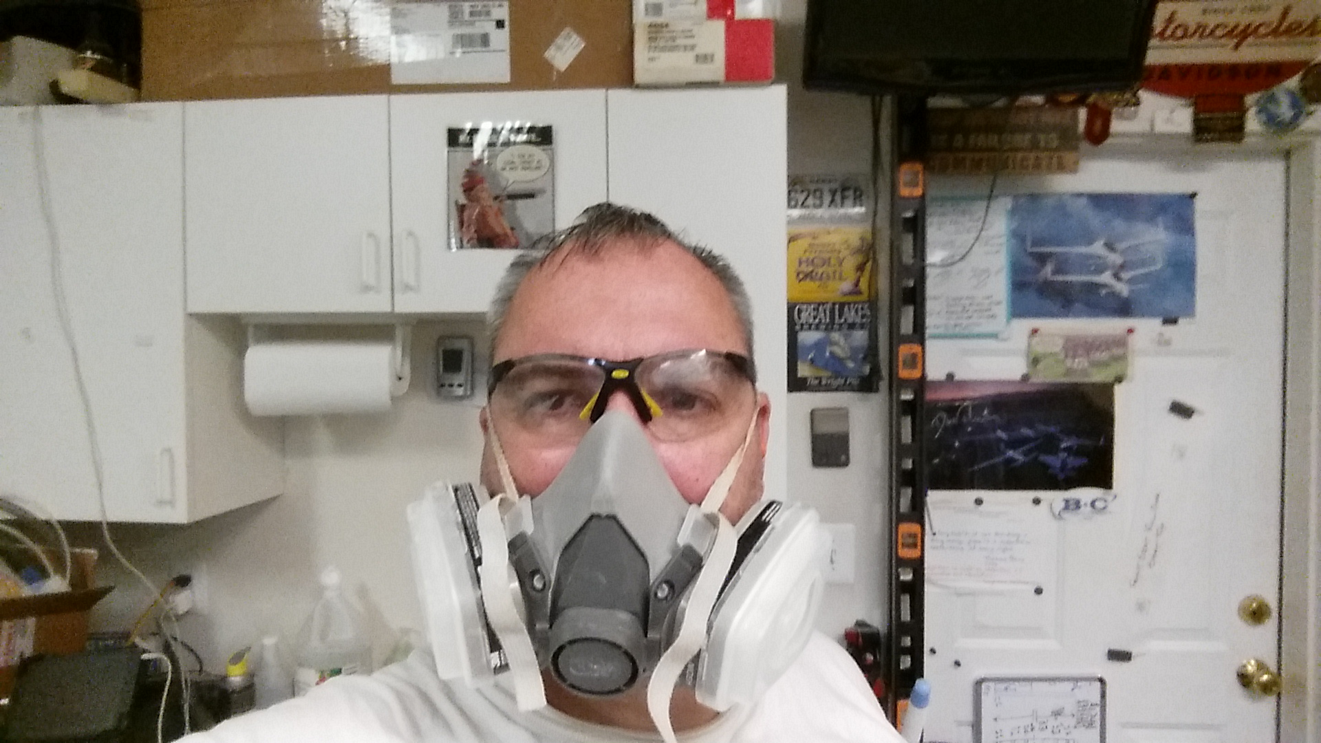
Here’s a couple of self portraits that I took with my Darth Vader-lite gear (I figure every now and again I should show the FAA that I was the guy actually doing the work!).
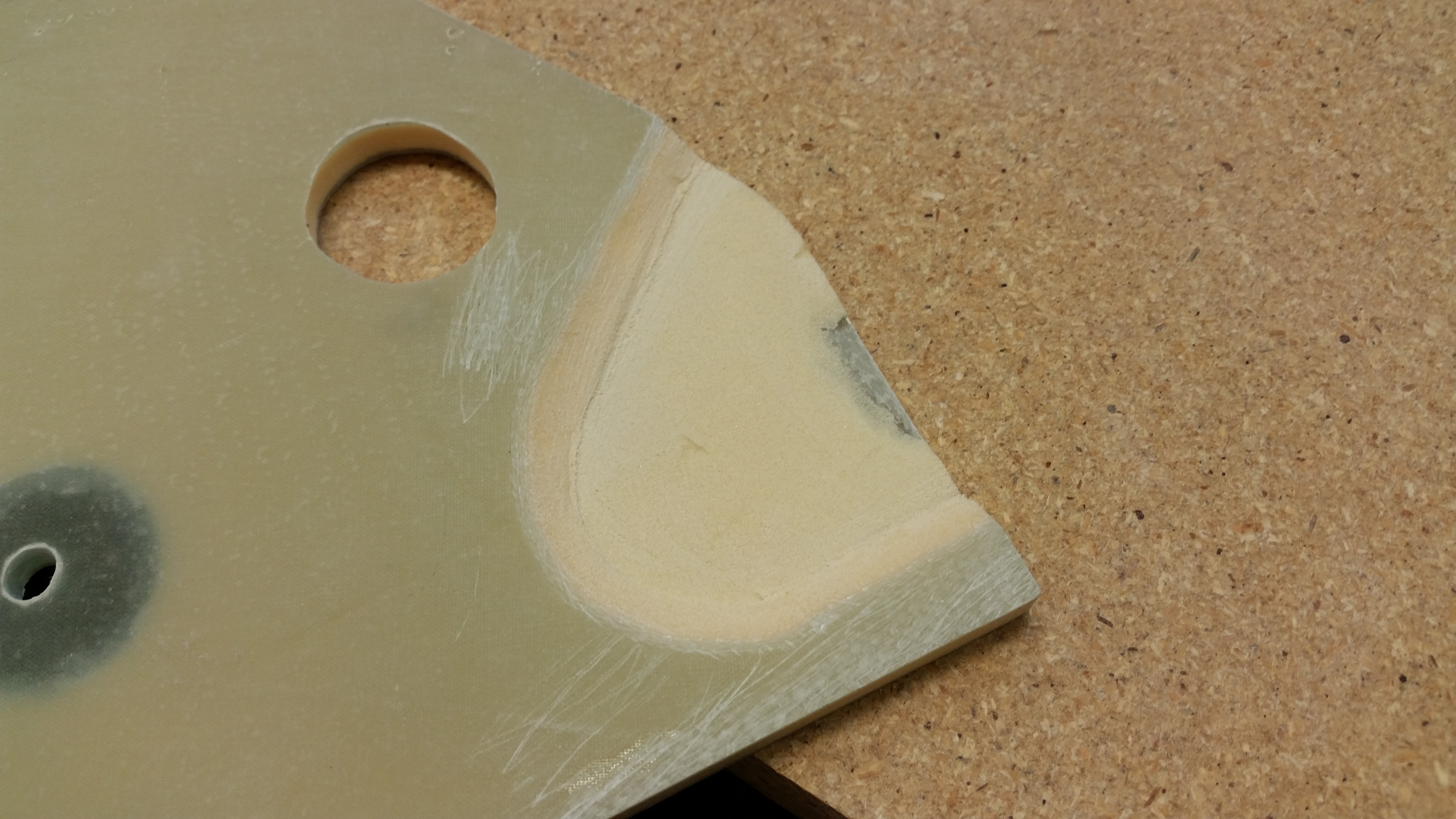
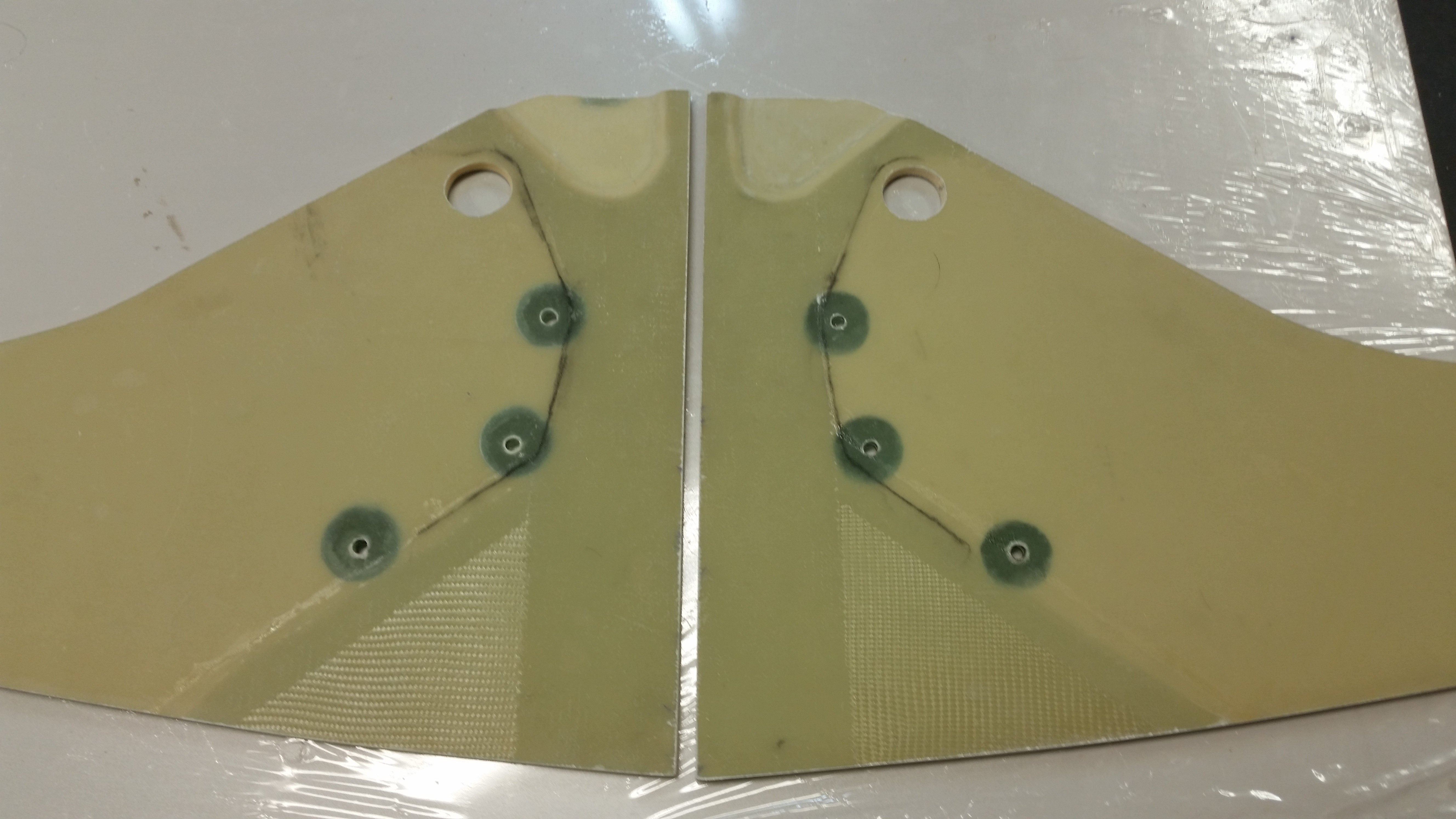
And here are the depressions ready for glass after I refined the beveled edges with the Dremel tool.
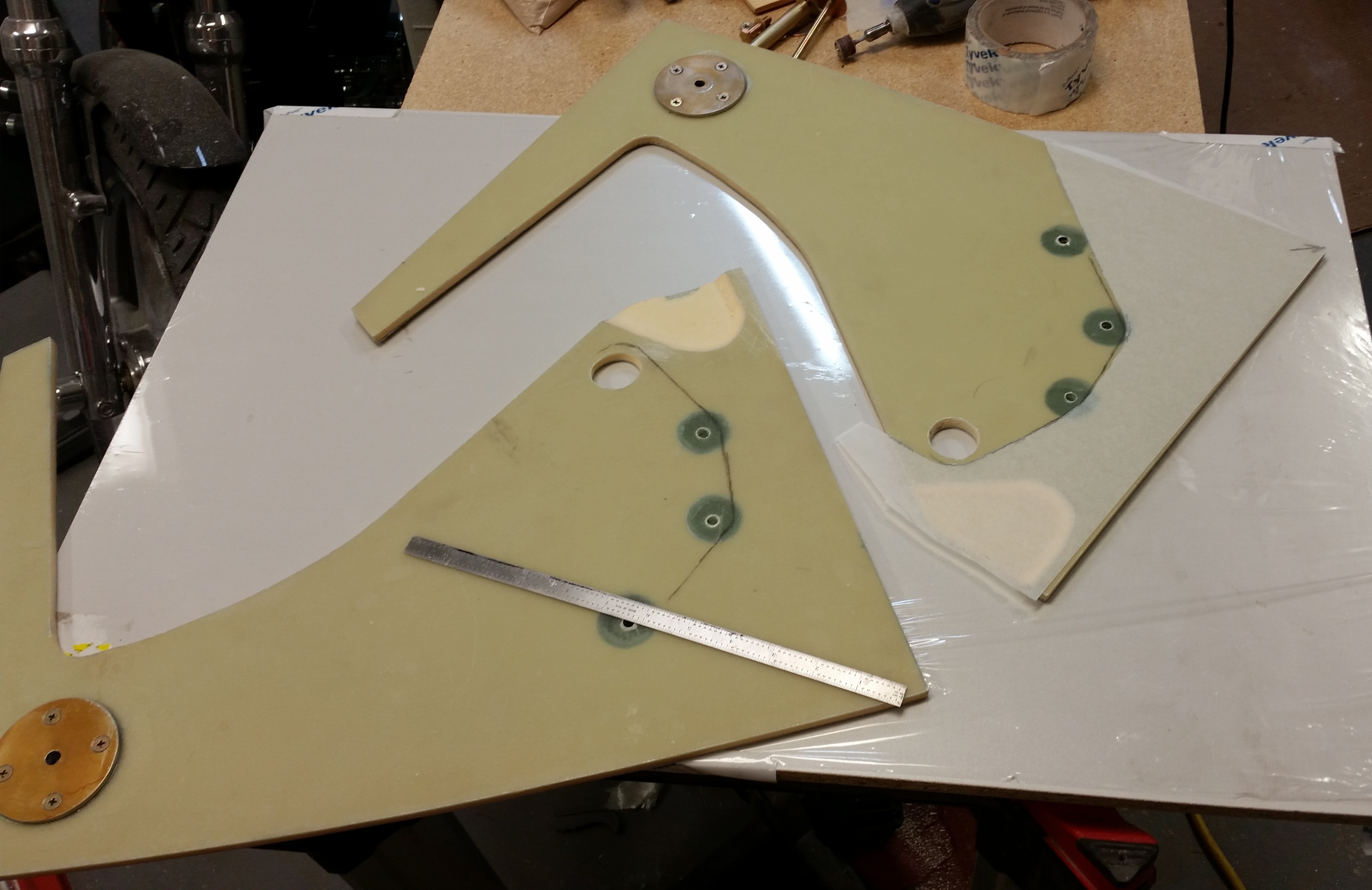
With the glassing ready to commence, I needed to make a template of the areas I intended on glassing. I wanted to stay clear of the gear actuator mounting brackets (that bolt into the 3 hard points) as to not mess up the set internal dimensions of NG30 components (e.g. relationship between actuator mounts at the aft end of the NG30s and the NG6B, nose gear strut pivot at the forward end of the NG30s).
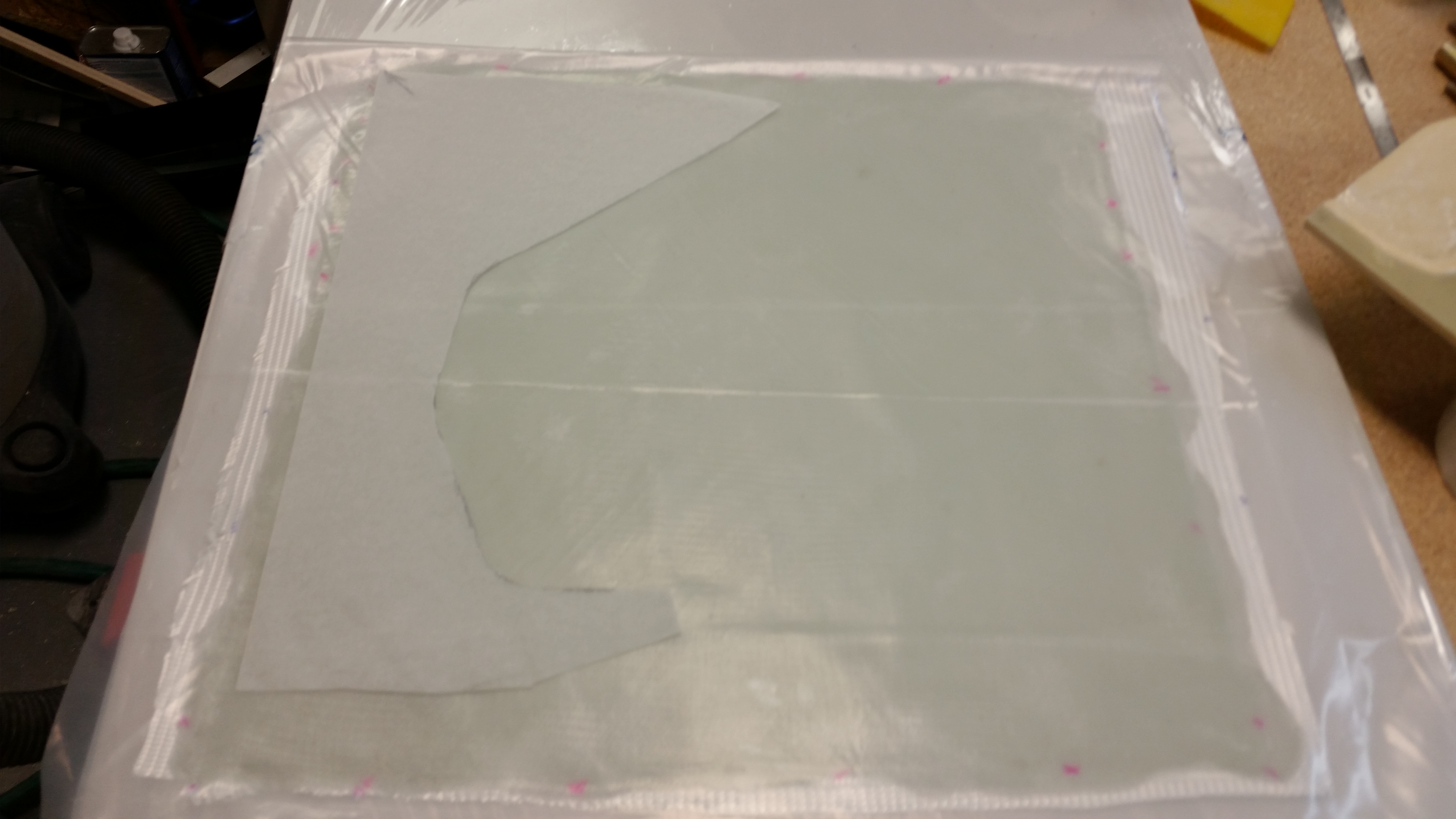
And then I had to do something that I haven’t done in quite a while . . . cut glass off the roll! After making the template, I calculated that I needed to cut two 15″ x 15″ squares of BID for the pre-preg setup.
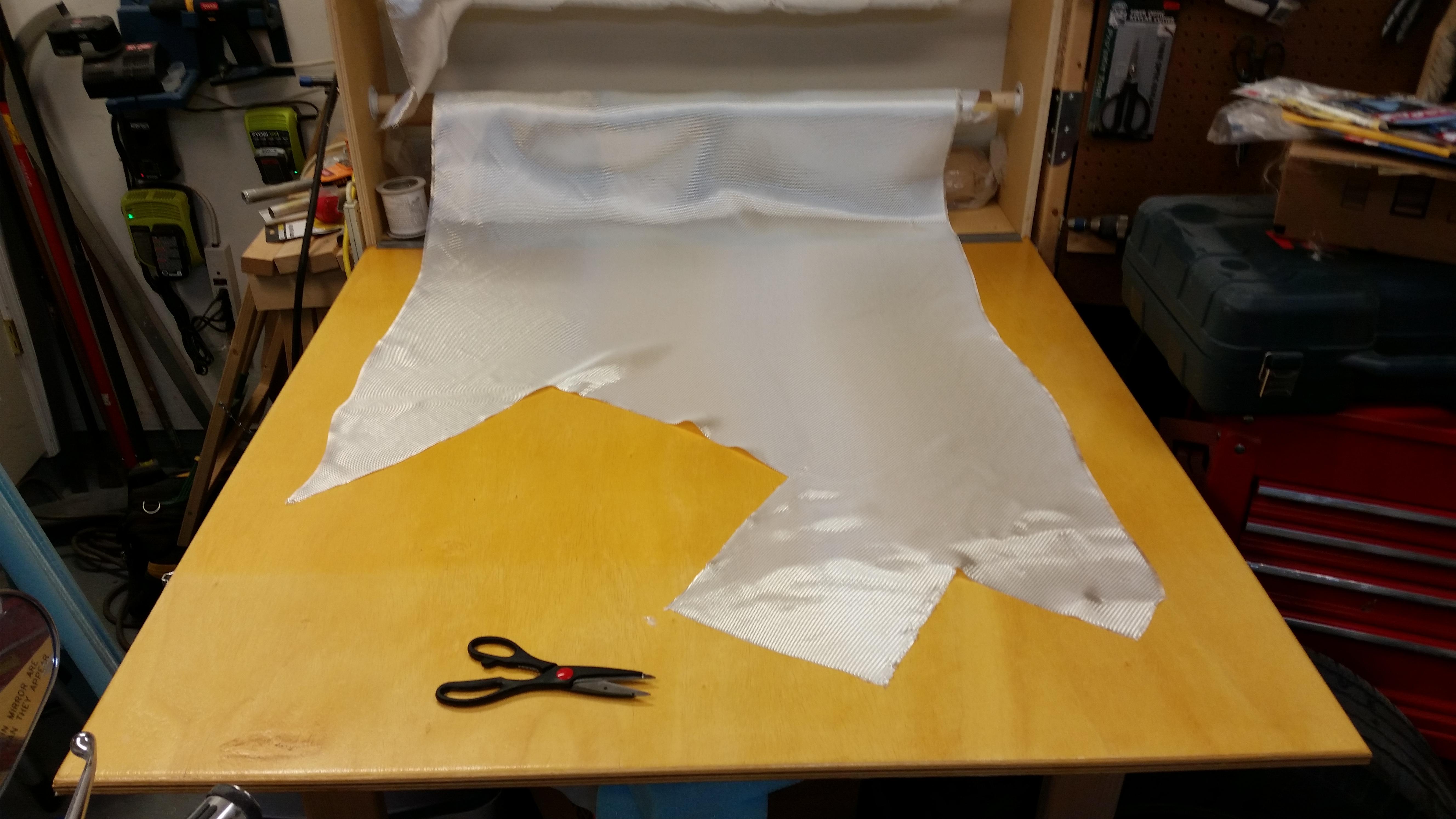
Here’s the 2-ply BID pre-preg (“poor man’s”) setup ready to go.
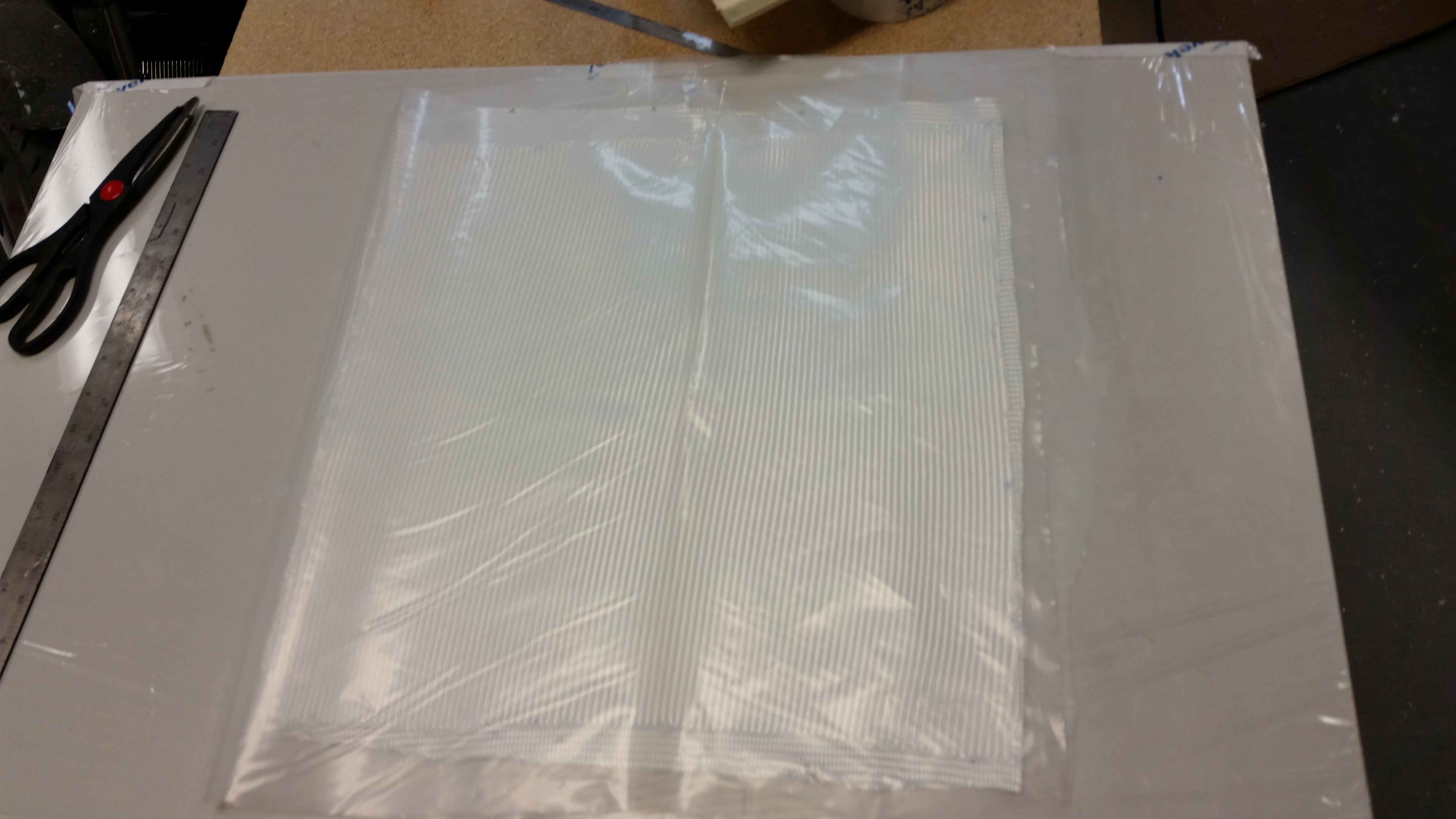
And then I added epoxy–using fast hardener–to wet it out.
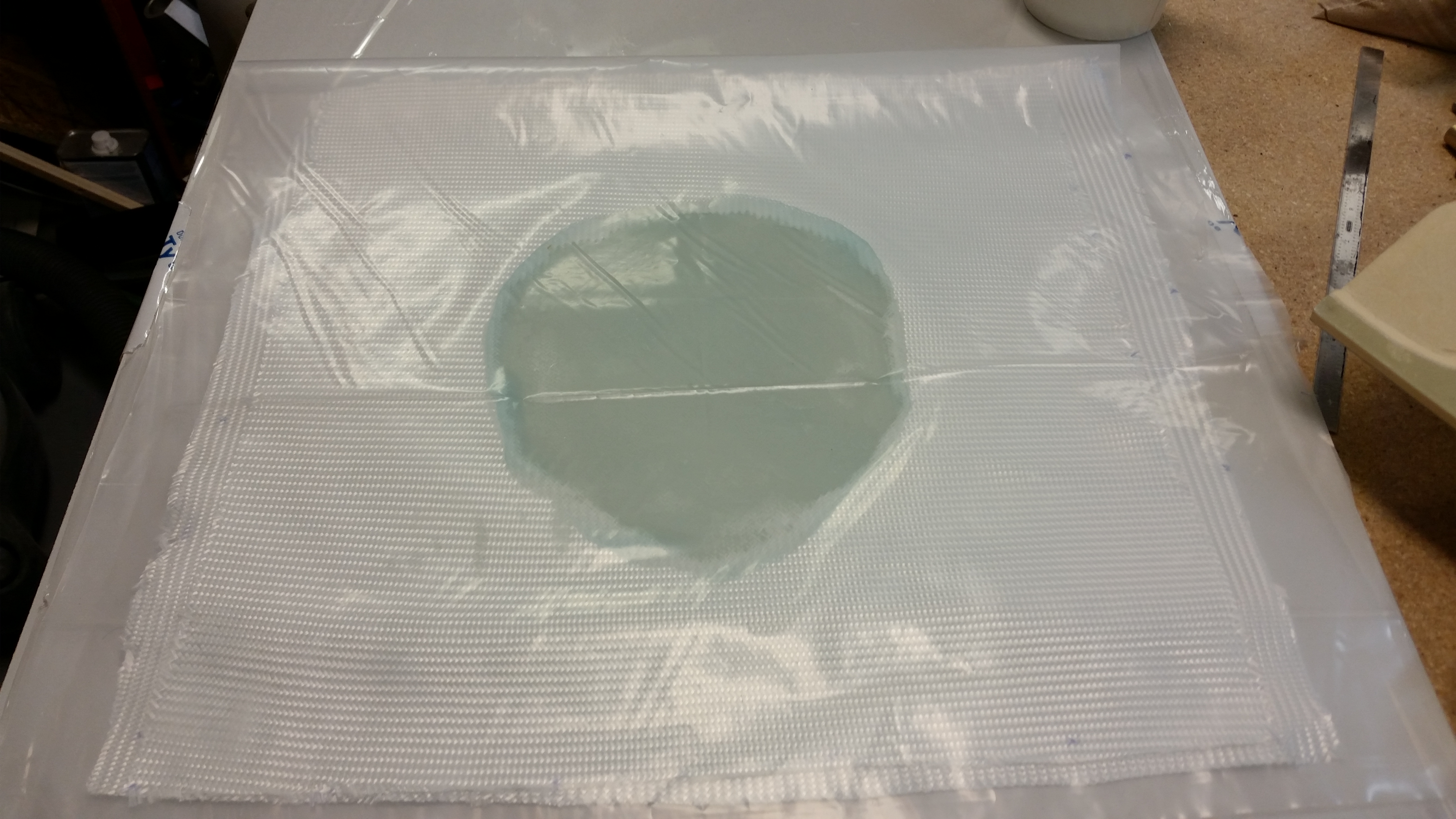
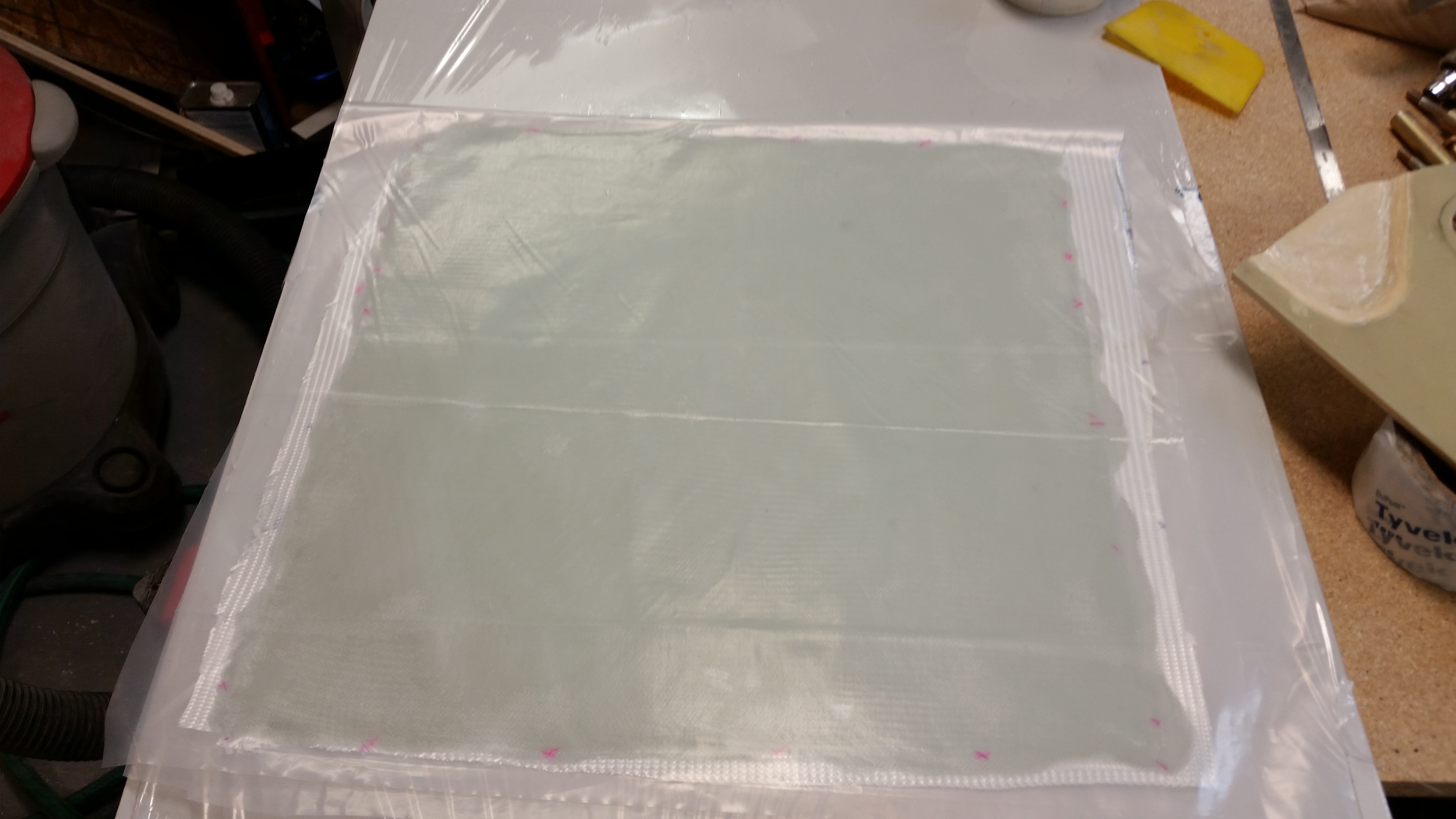
Once the BID was fully wetted out, I used the glass template that I had just made and cut out the two pre-preg setups for glassing the NG30s.
I realized if I had staggered the sides a little better, I could have conserved more BID . . . oops!
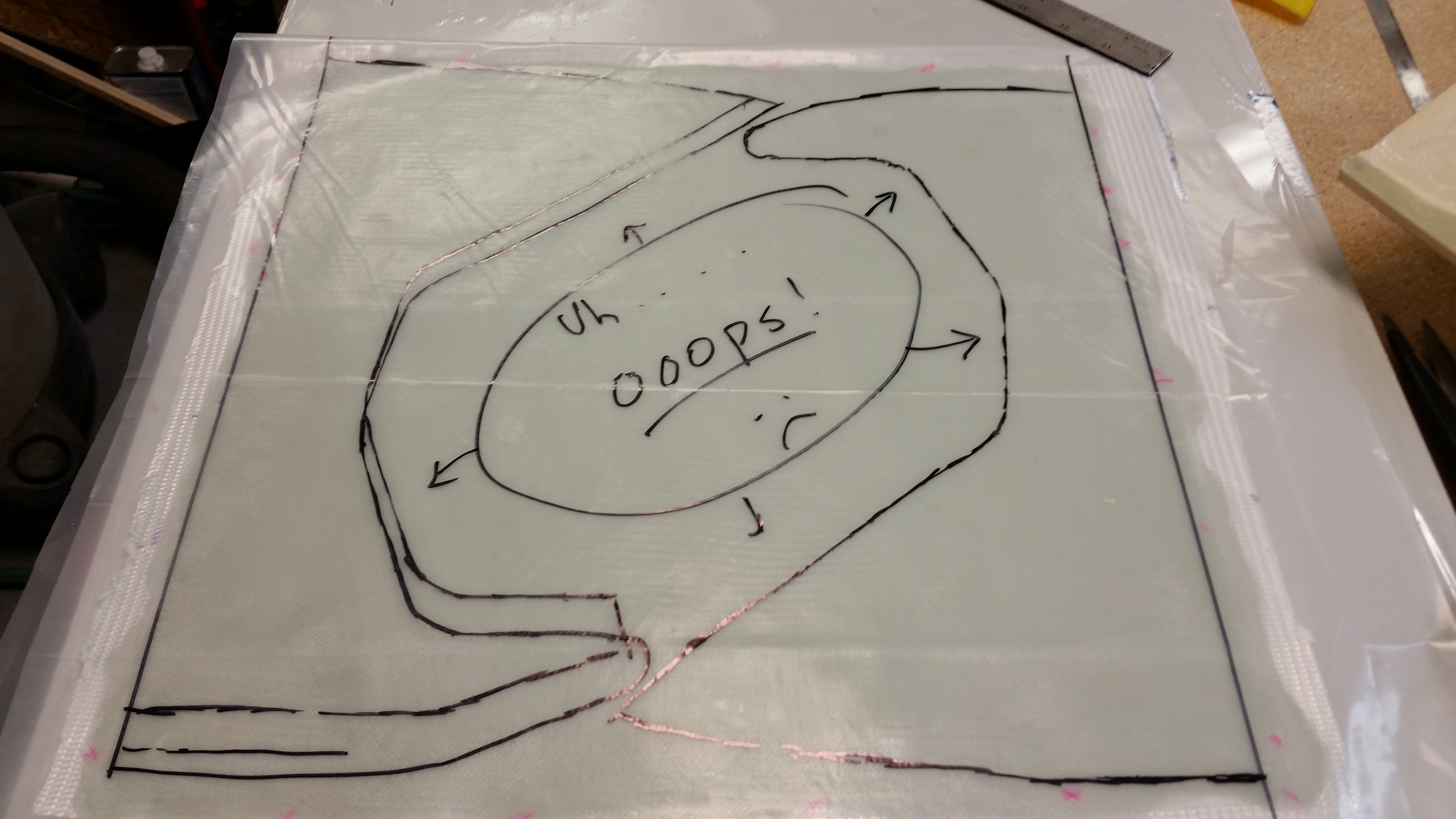
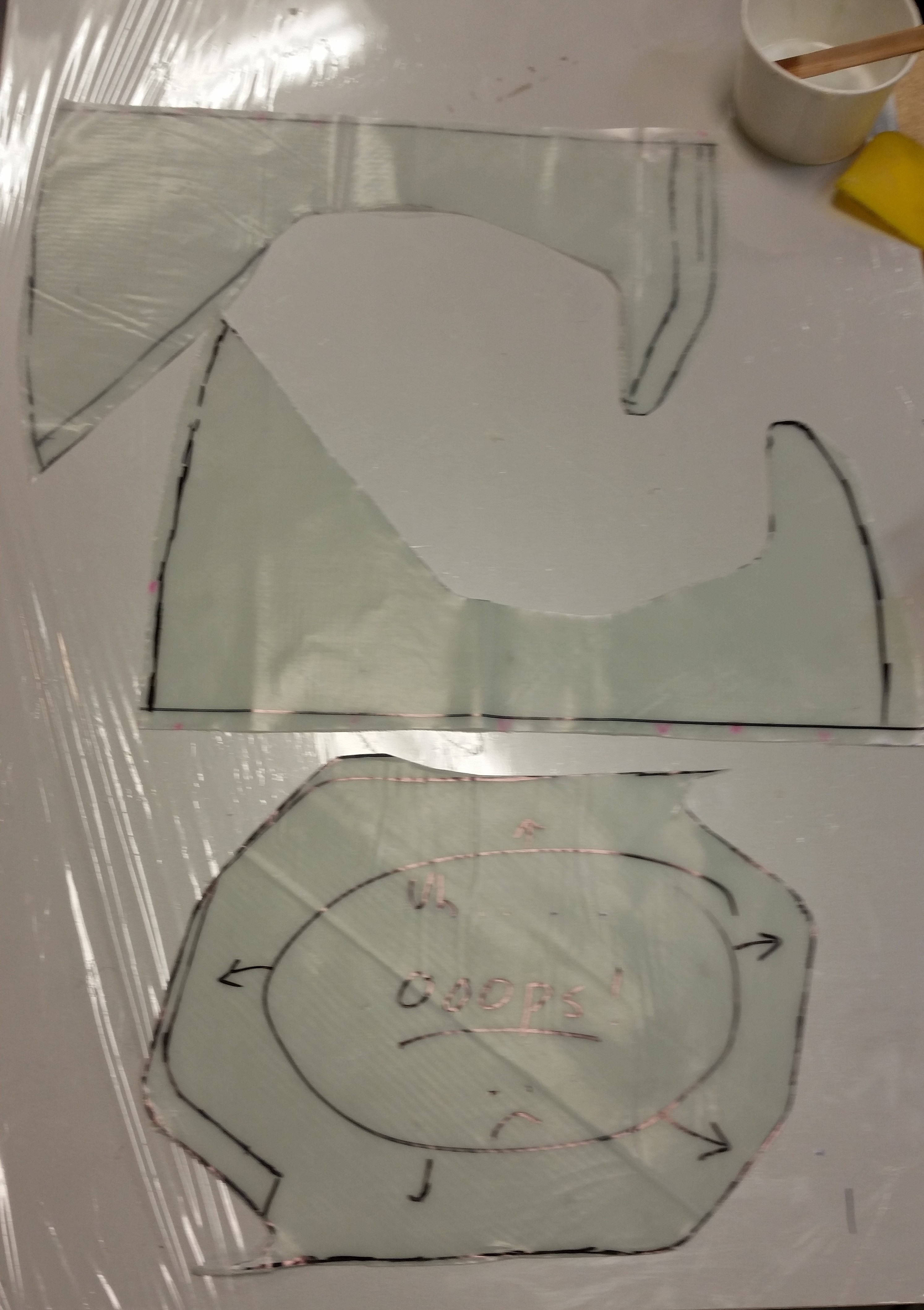
I then cut out the two BID pre-preg setups.
I set the “oops” section aside so it will cure flat, at which point I’ll use some of it later on by cutting it into 1/4″ strips to use as filler material when I have to increase the depth of both my stock strut cover (SC) and nose wheel cover (NB) that I bought from Feather Light… tweaking these parts is a second order affect that is a result of having to cut the gear strut channel deeper to get the nose wheel to set fully into the belly of the plane–which differs from the original plans where the nose wheel hangs down below the airplane by just a bit.
I then laid up the BID pre-preps on the inboard sides of the NG30s. After ensuring the layups were good, I peel-plied the critical areas/edges. As per my plan, I was able to just skirt the edge of the actuator mounts by about a 1/16″ to 1/8″.
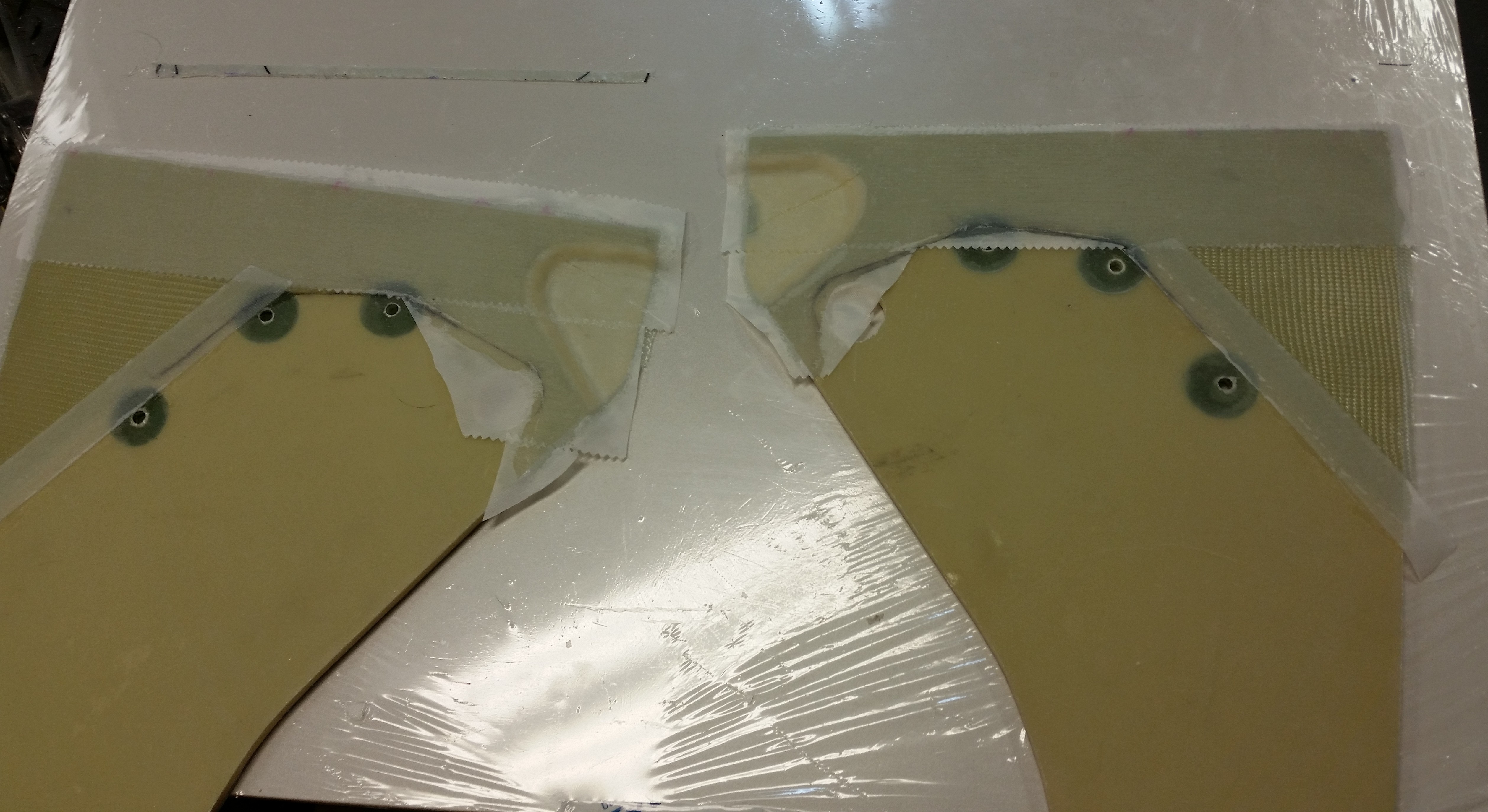
I noticed after laying up the glass, that the glass at forward top of the depression would not lay flat on the foam on the right NG30. I kept my eye on it and finally after messing around with the pesky glass for a few minutes, to no avail, I simply covered that area with Saran wrap, put some cushioning material on it to flatten out the invariable ridges from the plastic, and then threw a sandbag on it to keep the glass weighed down while it cured.

Now, onto more noise-making activities!
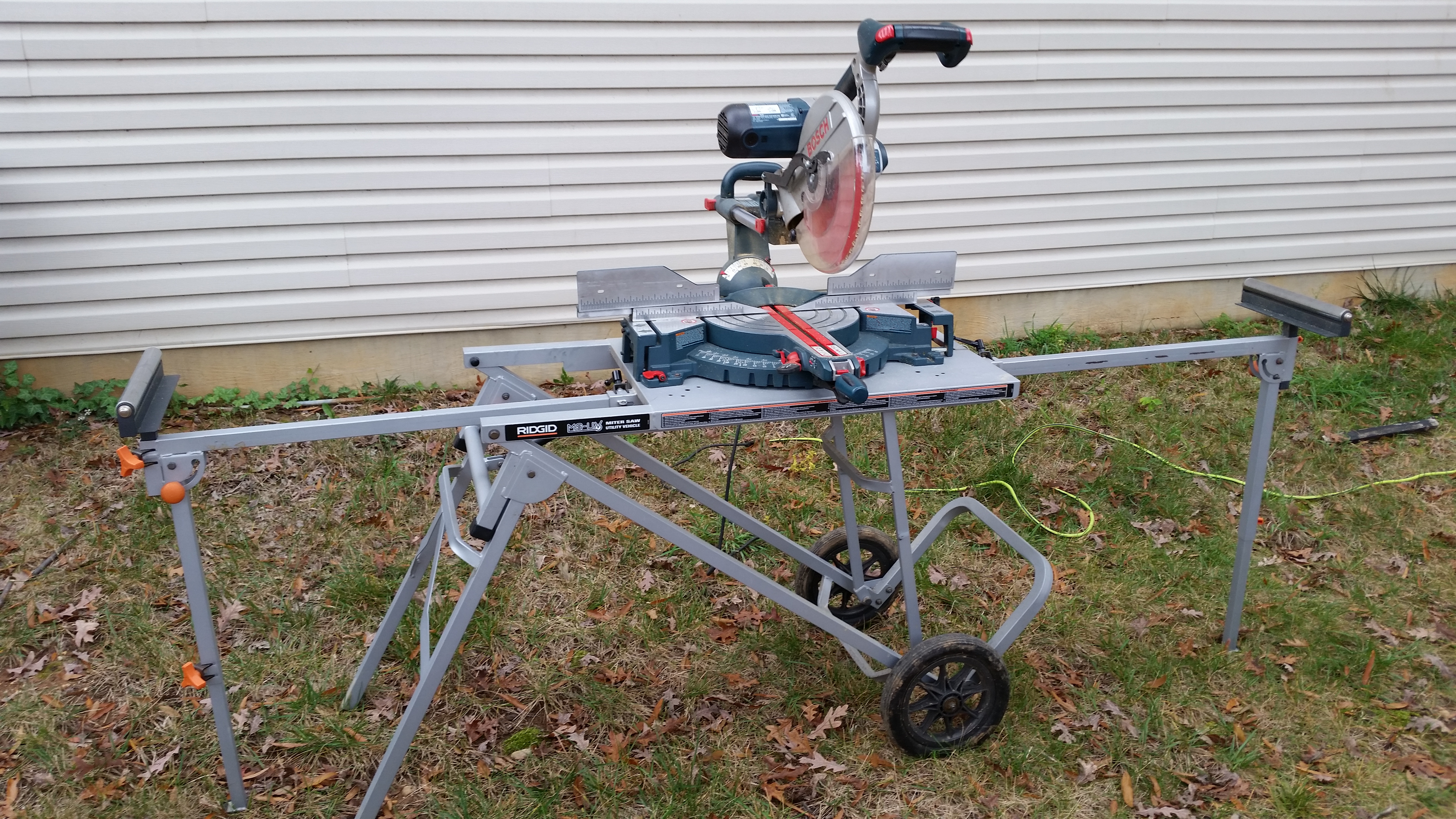
I pulled out the big dog to make some real noise! This sucker will cut anything!
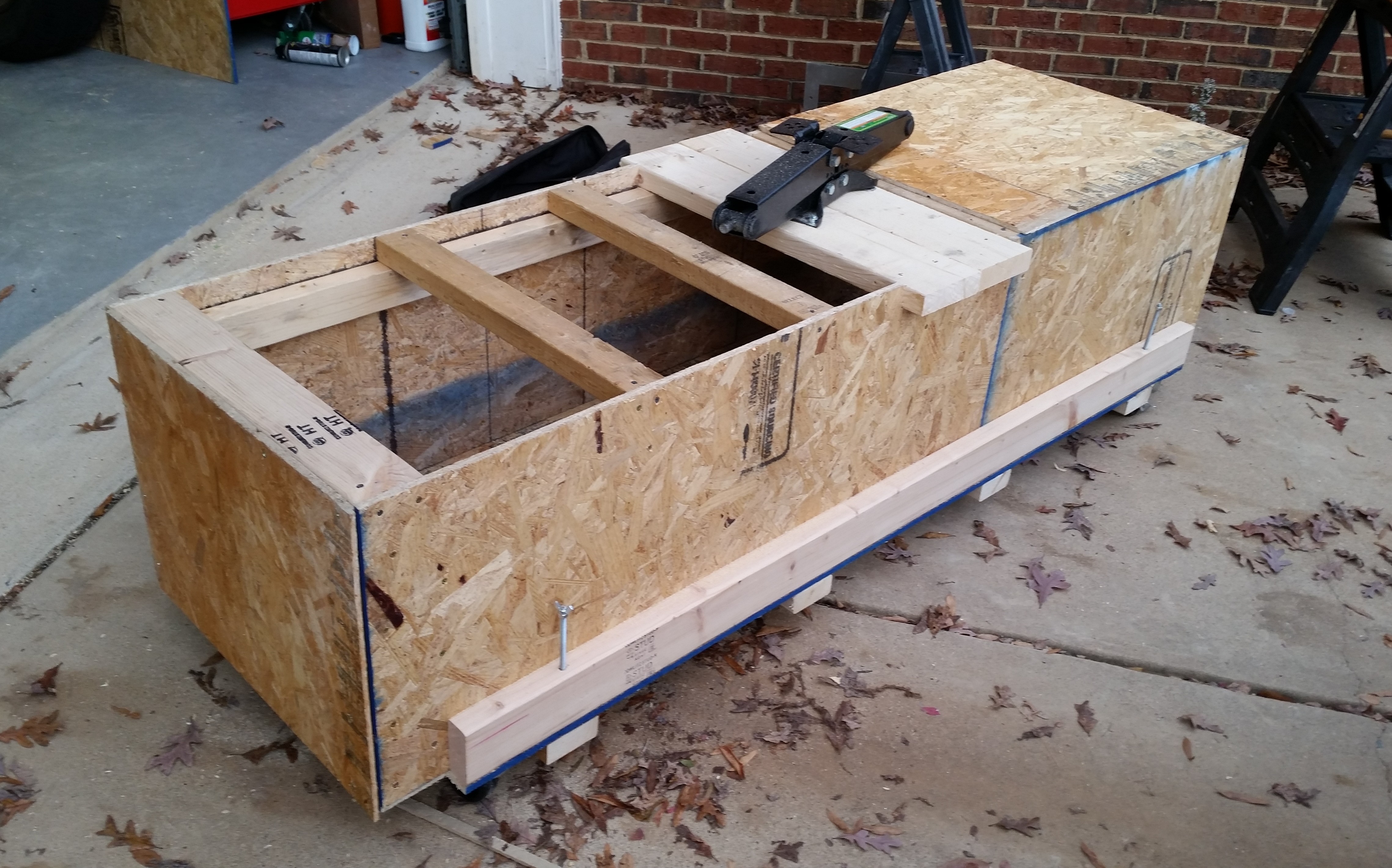
Here’s the stash of goodies that will turn into an operational fuselage dolly.
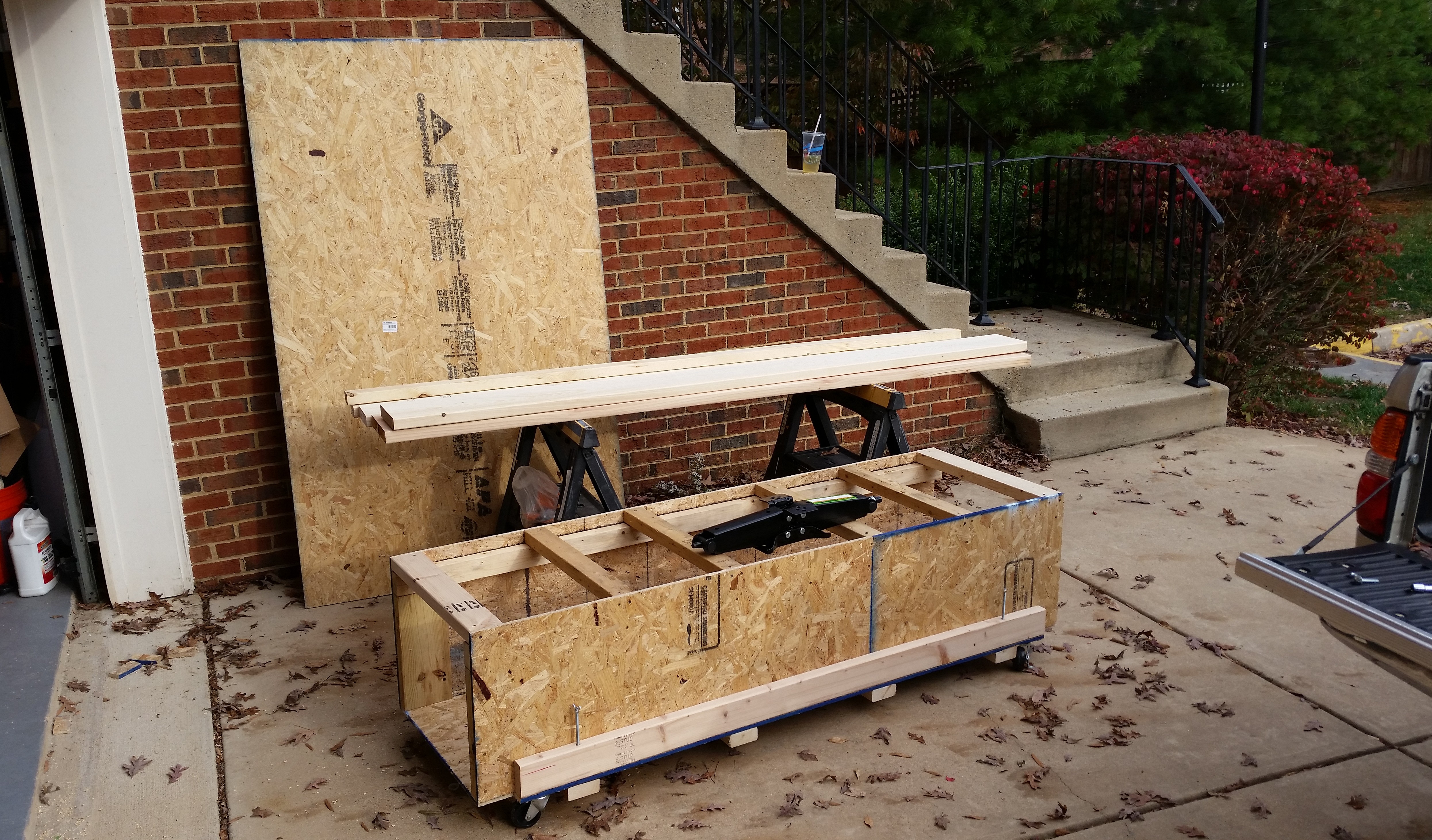
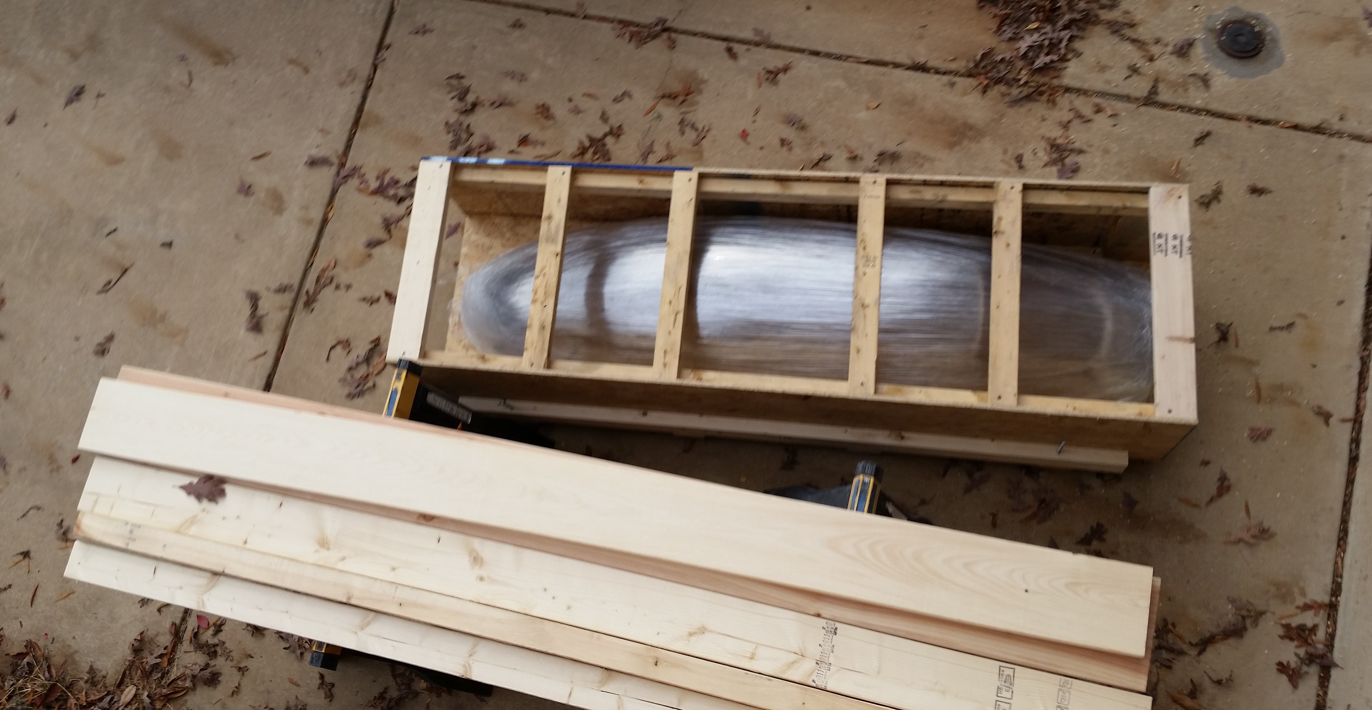
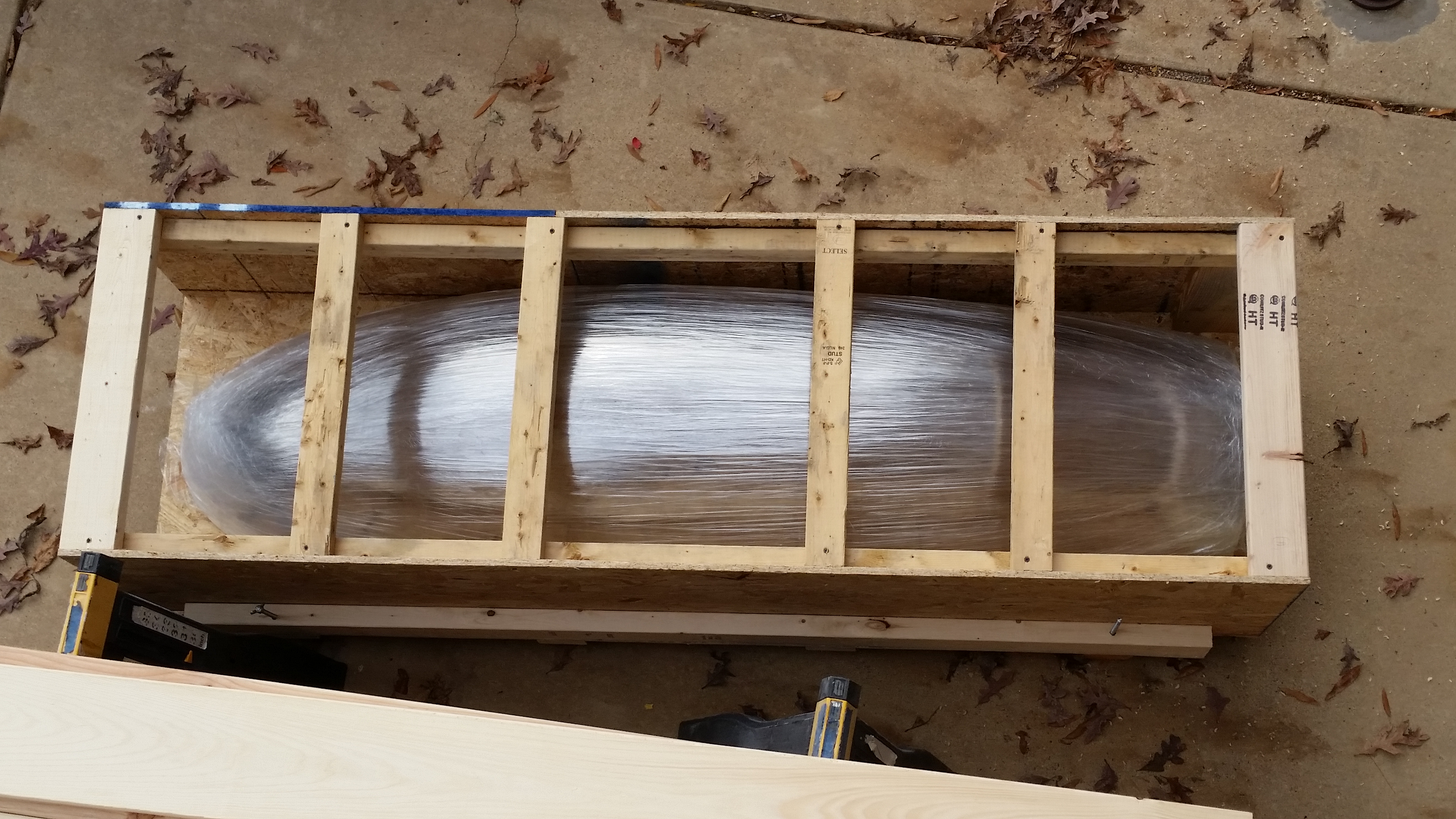
I pulled the canopy out and placed it into the fuselage dolly . . . it fit perfectly!
I then notched the sides to make a mount for the . . . ???
(what could it be?!)
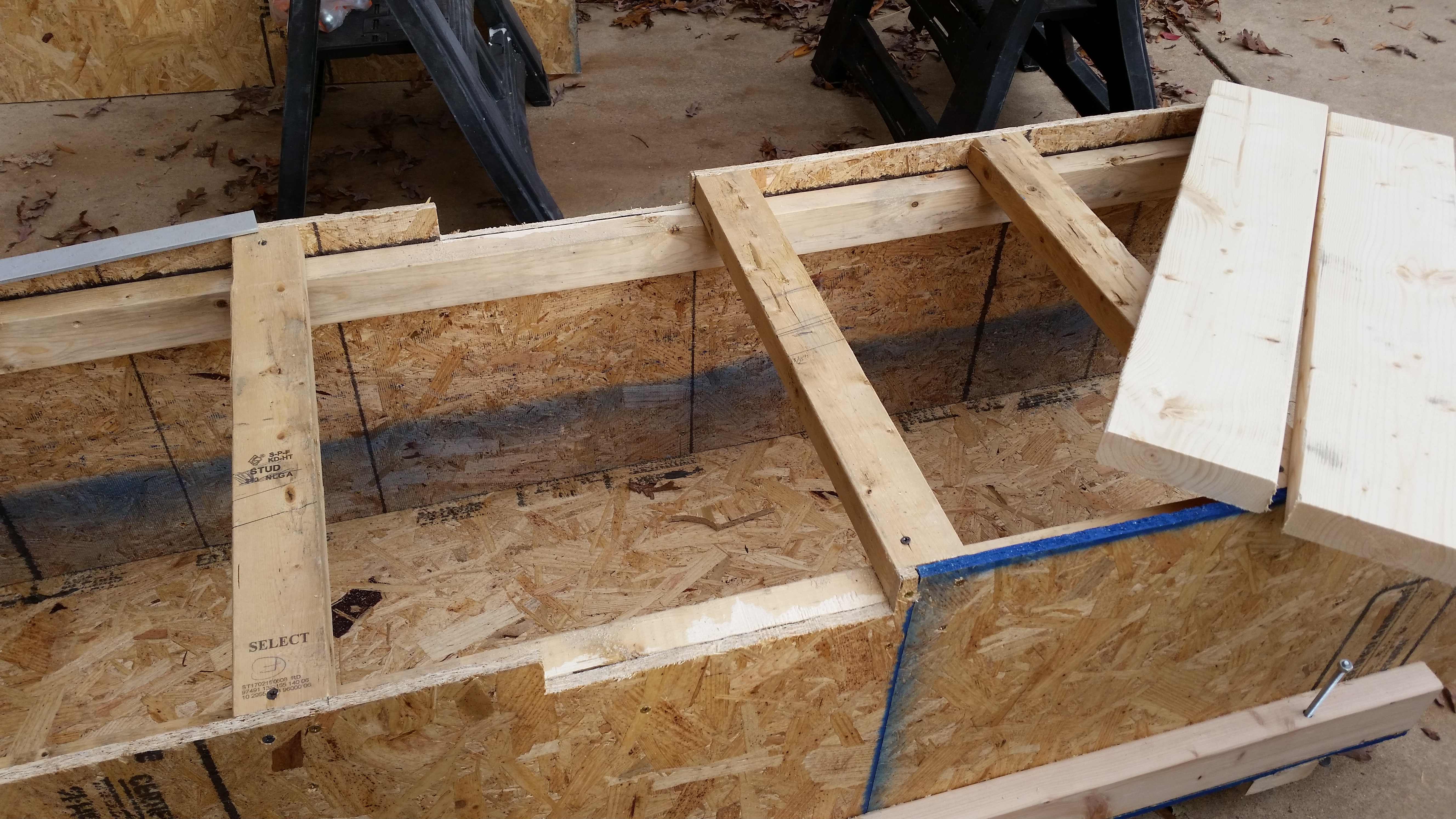
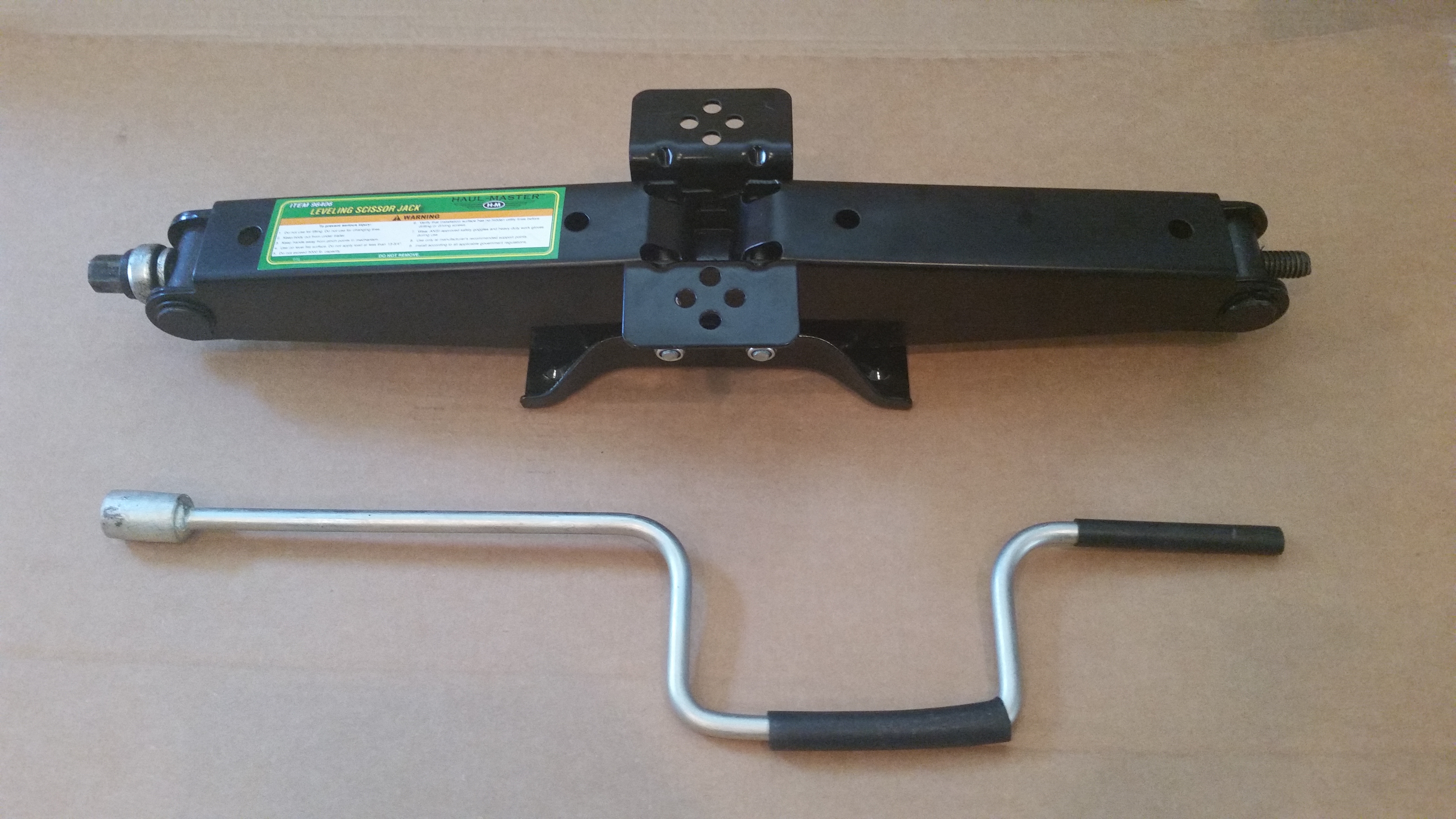
Yes, it’s a scissor jack from Harbor Freight! At last, my secret is out!
As you can see in the pic below, I offset the jack slightly off center, a few inches towards one end of the dolly to allow the extension to meet the side near the front corner. This will allow me to operate the scissor jack being off to one side of the centerline and not have to work with an airplane nose or tail in my face.
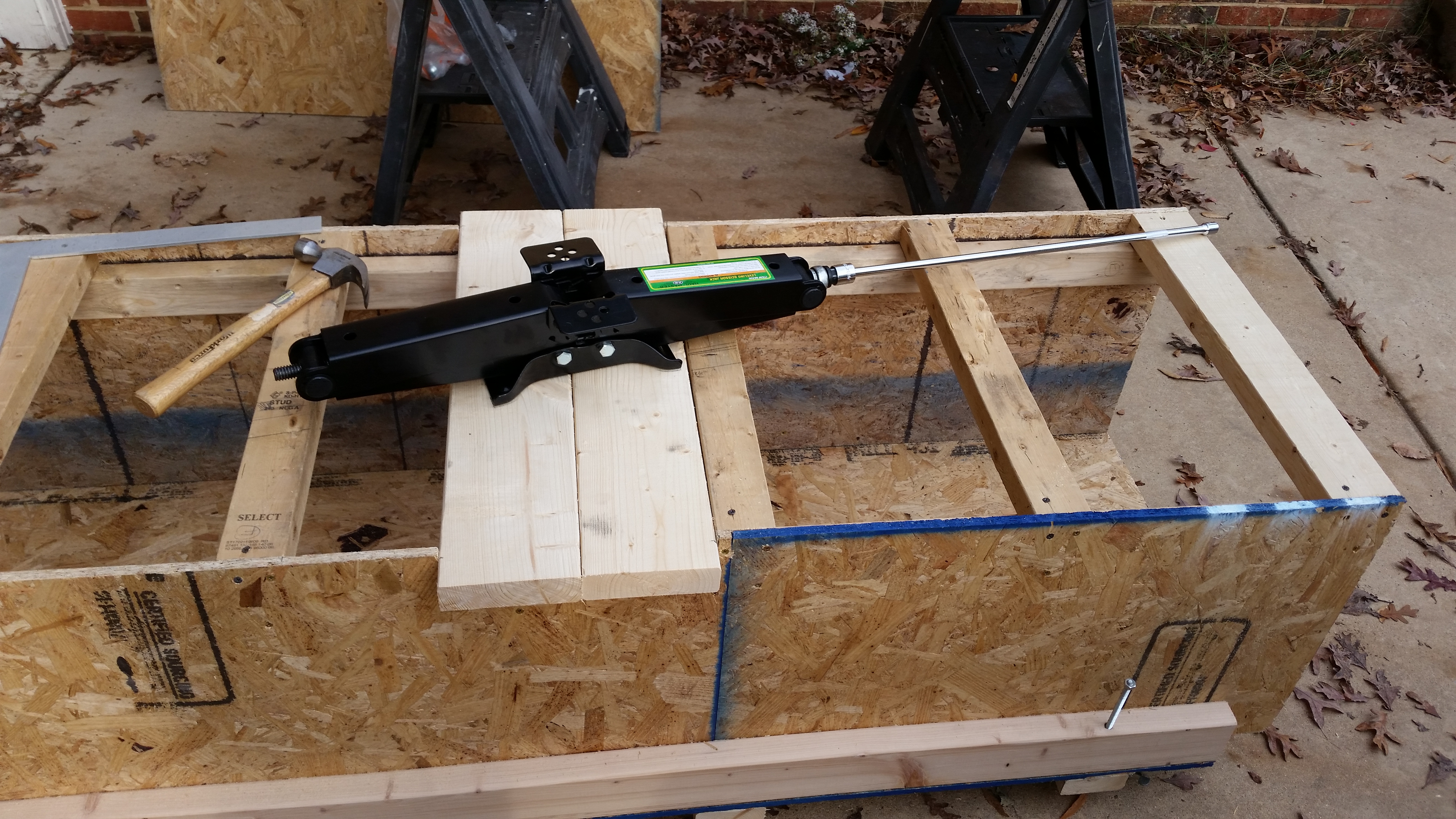
Here’s another shot of the scissor jack. When extended the scissor jack gives me a good 19″ of added height. I think you can see where I’m going with this, so I’ll have the base table height, and when need be I can raise the fuselage up from around 2′ off the floor to around 4′ up.
Once I had the location figured out, I drilled the four 5/16″ holes for the carriage bolts.

I then installed the carriage bolts.

After cutting the top two 2×6 pieces for the screw jack mount, I also cut & installed another 2×6 support in the front inside at each corner on one end (I had already installed these at the other end).
With the inside 2×6 supports mounted, I was then able to finish installing the final two lag screws for the wheels at the corner.
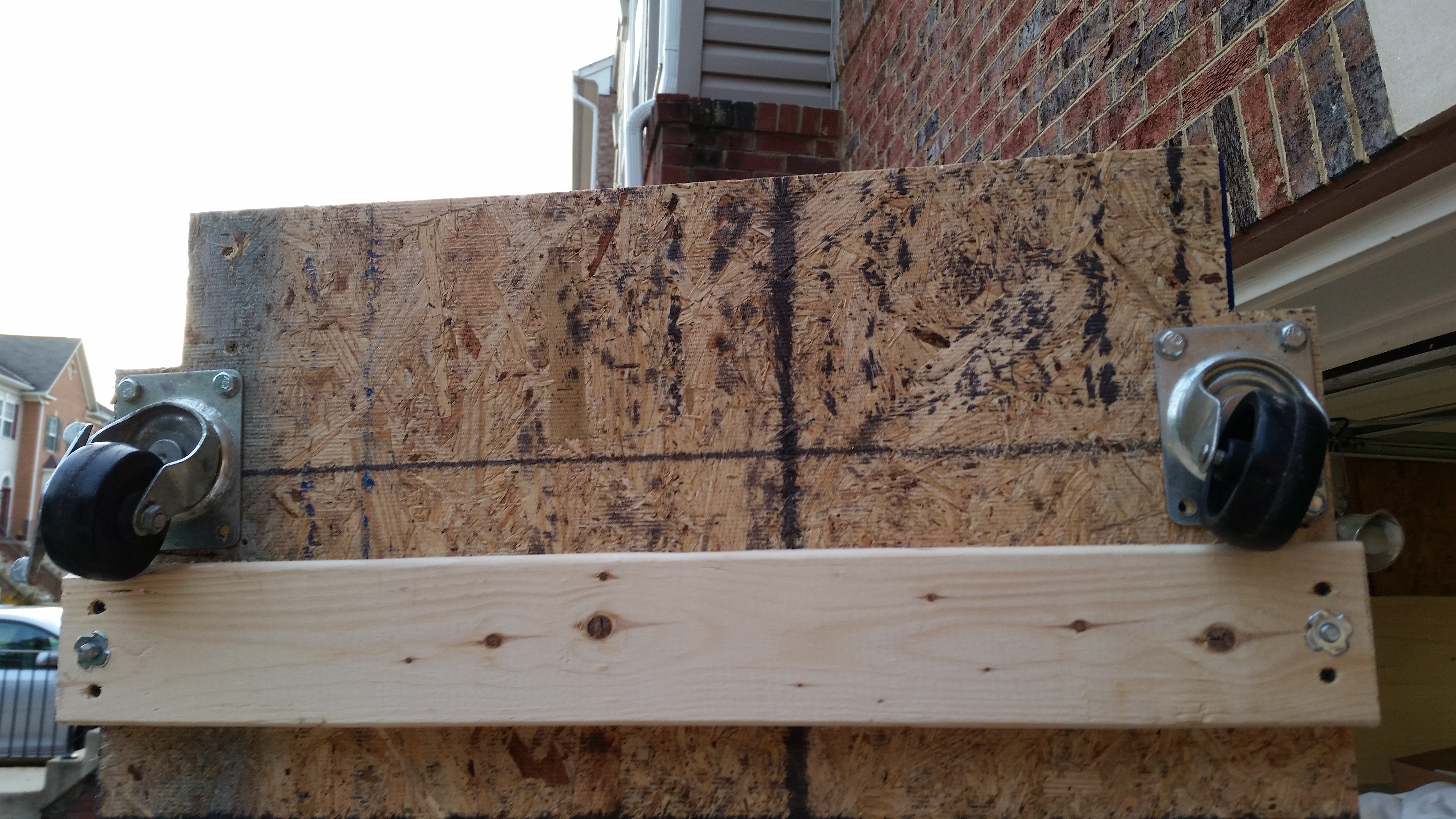
I then cut some shed siding that I had sitting around & mounted it in place. I left one top side open to use when I clean out the lower fuselage dolly before placing the canopy inside of the box. It will then be sealed completely (via wood siding) to protect it.
Below is the last shot I took of the fuselage dolly in its latest state before I packed it back up in the garage and quickly changed to get on the road to see my buddy Doug.
My good friend Doug & I were Air Force Bomb Squad Technicians (Explosive Ordnance Disposal) stationed in England together back in the 1980’s. It was great seeing him & catching up, and since he’s a pilot, we had some good conversations about a variety of Burt’s creations!

When I returned home after having dinner with Doug, I knife trimmed & sanded the edges of the NG30 layups from earlier. I’m really happy with how they turned out & think that they will be very beneficial in their new state.
Tomorrow I plan on working on the outboard sides of the NG30s (more layups), the fuselage dolly and canard.