
Before I get to the “enigma” part of this story, I wanted to show you one piece of what Marco & I were into last night. We started off out in the shop and of course had a myriad of discussions on all things Long-EZ. He brought some Long-EZ seat cushions he has and we tried them out both in the front & back seat. This visit is the first time Marco has sat in my fuselage, and he did note the difference in feel between my 1.4″ wider cockpit vs. his stock flying plane (he widened his build Long-EZ fuselage 2″).
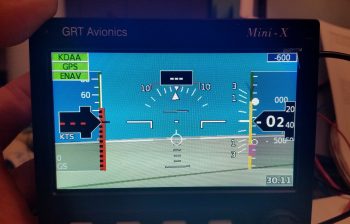
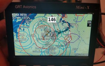
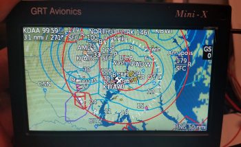
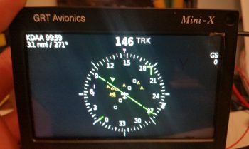
The more exciting part of his visit is that right before we went to dinner I hooked up a 12v battery to charge while we were out. Then, when we returned, we fired up the GRT Mini-X EFIS for the first time ever. Marco was curious to see how it looked and requested that we take a look, so we messed around with the screens, menus, features, etc. for a good while. We didn’t take any pics last night, but below is some of what we saw with just power and the GPS antenna hooked up to the Mini-X.
Primary Flight Display (PFD):
Navigation Maps (Track up & North up):
HSI:
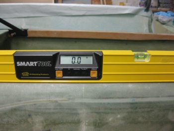
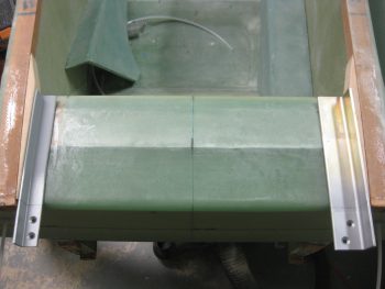
Today I started out by lifting the fuselage nose to get the longerons to a level 0°.
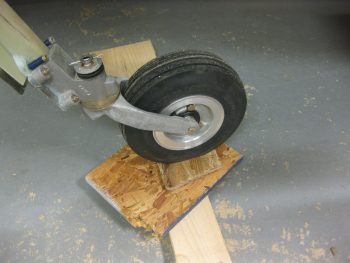
Longerons at a level 0°.
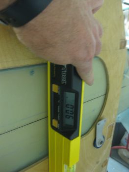
I then checked the firewall and it was dialed right in at 90°, perpendicular to the longerons.
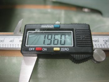
I calculated the thickness of the firewall (since I haven’t glassed on all the BID yet) at 0.355″ and simply rounded that up to 0.36″ and added it to the 1.6″ for the part of the engine mount extrusion sticking out aft of the firewall for the engine mount to attach to.
After removing the firewall, I mocked up the engine mount extrusions (remember, the top ones are a mixture of 4130 steel on the left side and 2024 aluminum on the right) and then checked the WA16 Spruce wedge spacers. Since my fuselage is just slightly more curved, I cut the WA16s 0.4″ at their widest point vs the stock 0.3″. This of course turned out to be a wasted effort since even though the fuselage is more football shaped than stock, the plans 0.3″ wide wedge spacer dimension is still the correct size. Ahhh, so I did even more cutting and sanding to get these things thinned down.
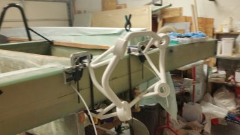
I then clamped and set the engine mount into place, only attached to the upper engine mounts for the initial look.
 This is where the ENIGMA part comes into play. I have no idea why, since I thought I was Uber diligent in my measuring of all fuselage dimensions at the beginning of this build, but the face of my firewall is setting at about FS 125.4 vs the plan’s FS 125.0. I have to admit I was remiss in double-checking the firewall dimensions when I installed the CS spar into the fuselage, since I assumed that my spar notches were good due to the fact that I did re-check their measurements. Plus, the firewall fit flush and appeared aligned, which it is . . . just 0.4″ aft where the face of it should be.
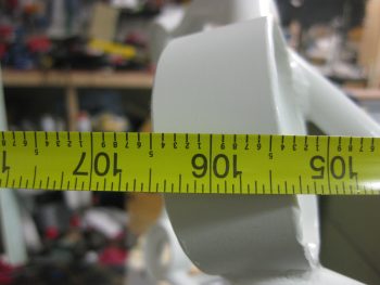
The real affect, although over-comeable, is that the top set of engine mount brackets are setting at FS 134.5 vs FS 134.2. 0.3″ may not seem significant, but it certainly is to the W&B when you’re talking about the mounting of the 250+ pound engine, the heaviest component on this entire craft.
My initial concern was that if I simply move the mount closer (which will require some trimming of the upper engine mount stems) that it would negatively effect the clearance of the forward-mounted engine components. But since I’m using Electronic Ignitions in both magneto mounts, they won’t require the forward space that Slick mags do. Thus, if I trim a hair over 0.3″, and mount the engine with it’s normal engine mount stem to firewall spacing, I should be very close to spot on with the FS 134.2 engine mount setting.
[BTW, the measurement below was taken from the face of F28… so, 28 + 106.5 = 134.5].
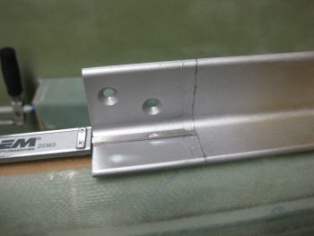
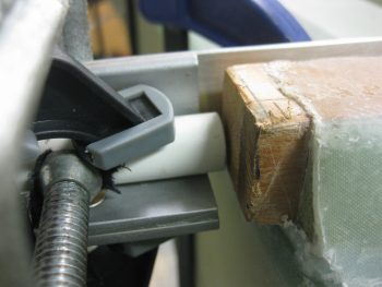
This shows the gap between the end of the right longeron and the upper right engine mount stem. Note that if the engine mount stem were left at the length in the pic below, it would actually be embedded into the firewall. The aft face of the firewall will be just forward of the double horizontal extrusion plate shown just underneath the engine mount stem.
Tomorrow I’ll actually trim the engine mount (too late tonight due to noise) and continue to work the engine mount extrusions. I do plan on getting the layups & upper engine mounts in tomorrow. Also, as you can see –at least for the time being– I’m pretty much done with Chapter 16, Controls. Finally, there’s some important info concerning my upcoming build schedule in the project update post.