
I started off today by spending a good 45 minutes mounting the elevators to the canard. The hinge pins went in significantly easier than they have in the past, but I still have to flip the canard right side up to get the pin tips to natural hang point down inside the elevator tubes to get get them through the middle hinge pin bracket.
After getting the elevators mounted, I then gathered up the hardware & attached the elevator push rod end to the outboard side of the right torque tube offset arm.
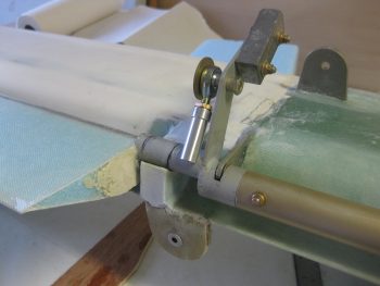
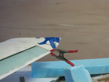
With the canard & elevators remounted, I then clamped the outboard ends of the elevator to the outboard ends of the canard to set the elevator at 0°. I know that the elevator is positioned just a bit lower than this during cruise flight and I would intuitively think that the control stick position would correlate with the cruise position, but since nothing is referenced in the Roncz canard plans I went with the original Chapter 11 plan’s “neutral elevator” position… although I guess that could be interpreted a few different ways. Nonetheless, I called this 0° neutral and rigged the elevator control push tube accordingly.
[A side note: for some reason my elevators are about 3/16″ off between the two sides at the outboard tip. I’ll use the hot weather trick when the weather gets hot again next year to straighten them out. Not sure why they’re off, perhaps they settled in differently during storage].
With the elevators pinned at 0°, I then set the control stick positioned 5° forward as per plans. I then marked the CS136 control tube, cut it and then drilled & riveted the rod end into place. I then mounted the elevator push tube to make my first officially moving control surface!
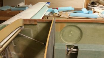
Here is the elevator with the control stick at neutral.
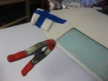
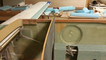
And again with the control stick full aft.
And the stick full forward.
With the elevator rigging completed, I then turned to finalizing the installation of my Infinity stick grip. To make clearance for the decent-sized cable exiting the bottom front of the Infinity stick grip, I needed to mirror the cable channel on the stick grip adapter onto the CS103 control stick tube. I sat in the pilot’s seat and set the stick so it was “clocked” correctly for my hand in a natural position. I then marked the intersection of the Infinity stick grip adapter and CS103. I then removed the stick grip and finished marking the channel that would need to be cut into CS103.
Since I haven’t been able to repair my downed Dremel Tool yet, I bought a cheap HF rotary tool for less than $20 and used that to cut the channel in my CS103 control stick. I left 0.8 of full tubing on the bottom of CS103 for strength and to have an area to drill & mount an AN3 bolt which will secure the Infinity stick grip.
Then, just to make sure I got it right, I climbed back into the seat and did one final clocking of the control stick position. I marked this final position at the base of the stick . . .
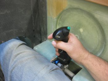
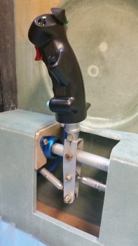
and then drilled the base to accept an AN3 bolt. I then attached the bolt & Voila! My front Infinity control stick grip is officially mounted!
Here’s a better shot.
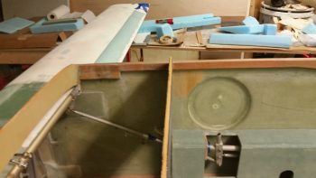
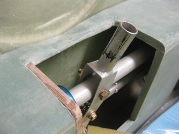
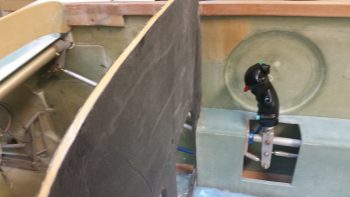
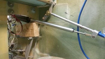
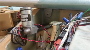
With the elevator controls rigged & my stick grip mounted, I then spent a few minutes getting a feel for how the Atkinson pitch trim assembly was going to get mounted into place. As you can see, I wedged the pitch trim assembly up into place using a 2×4 resting on the rudder pedal.
Here’s a shot from the front of the plane.
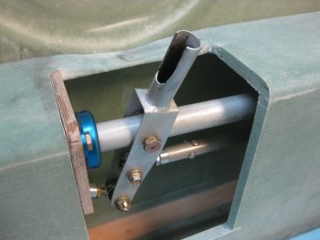
Here’s another shot with the actuator motor turned facing down, which may be required for clearance for the top of the nose. I also need to set my rudder pedals in their final position and check that my right foot has clearance with the pitch trim assembly.
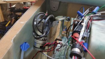
After I removed the canard, I tested moving the pitch trim assembly aft into the area between F22 & the IP. Although my foot could be very close to the actuator assembly (what isn’t a tight fit in a Long-EZ???) this may just be a viable mounting position.
Done with my pitch trim test-fitting shenanigans, I then moved forward with preparations for mounting the Trio autopilot pitch servo. Since I’m messing with the elevator control system, I figured now was a good time to knock out installing the AP pitch servo mounting.
If you remember back a few months ago, I had to send my pitch servo back to Trio to have them install the auto trim option. In transit back to Trio the Postal Service decided to drop kick this sucker… enough so that even buried in inches of bubble wrap they managed to ding a corner of the mounting baseplate. Well, most things work out for a good reason in the end, and this was one of those. Chuck at Trio sent me the dinged mount back with the upgraded pitch servo. I figured it was a novelty item until it came to actually mount the pitch servo. After digging into the installation manual & documentation, I realized this dinged baseplate will serve as a perfect mounting base for my pitch servo install!
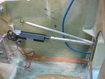
Although a bit out of order from the installation instruction sheet I got from Chuck, I cheated a bit using Nick Ugolini’s documented install instructions and went ahead with cutting the pitch servo pushrod to length (4.05″).
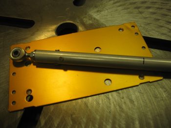
I then mounted an HM4 rod end on the freshly cut end (elevator side) using 1/8″ rivets.
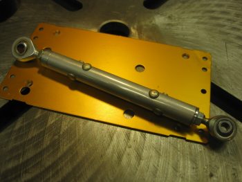
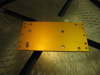
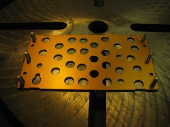
Then, to lighten an already light pitch servo mounting base, I made Swiss cheese of the previously dinged up base. More importantly, these holes are to allow flox to ooze through and better secure the mounting base. A final important note is that you can see that a compelling reason to use the dinged up mounting base is that it already has holes that align perfectly to the actual pitch servo base mount. I called Chuck earlier to confirm that it was ok to drill the out these mounting holes to accept a 10-32 bolt, thus allowing me to use Clickbonds to secure the pitch servo in place. Also, since the AP servos are sensitive to twist & minute movements that can cause slight errors in AP track functions, I’m using 3 Clickbonds per side to ensure the pitch servo is mounted securely and as little twisting action as possible is allowed during operation.
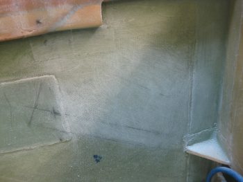
I then sanded the area on the right sidewall in prep for mounting the AP pitch servo.
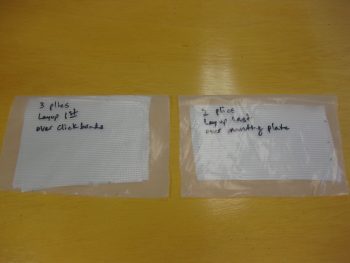
My last task of the evening was cutting 5 plies of BID for mounting the AP pitch servo. All the plies allow for 1″ overlap around the AP base mount, so they measure 5″ x 8″. The layup schedule for these will consist of the Clickbonds getting floxed into place, 3 plies of BID over the Clickbons, the base plate with liberal amounts of flox and then finally 2 plies of BID on top.
Tomorrow I’ll layup the glass for the AP pitch servo mount, and continue to work on the control system. In fact, I really just need to mount the aft cockpit-to-firewall control components and I’ll be finished with Chapter 16, so I’ll knock that out before moving back onto the wheel pants install.
Pingback: Infinity Control Stick Install | A Long Way Round the World
Thanks Brother!
Your site is pretty darn excellent as well! ;)