
Yes, 3 attempts it took bending aluminum tubes to make the fuel selector valve to fuel pump crossover line!!! . . . more on that below.
Today I started out doing some research on how to revive some old Chartpak dry transfer lettering sheet that I have. Apparently, over long periods of time they lose their transfer ability and they simply don’t work. Well, I tried a few of the home brew remedies of the Web and was able to get the letters off at least, but I just wasn’t overly happy with them.
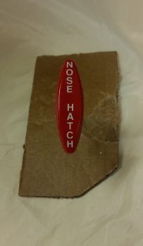
I wanted to use black characters on my red T-handle that I had designated as the Nose Hatch release handle, but it really didn’t look as good as I had envisioned. So I punted and simply went with the fresh set of white dry transfer lettering that I have on hand.
As you can possibly imagine, it’s difficult enough to get these letters to line up on a flat smooth surface, and another thing entirely to do it on a curved contoured surface. This is my excuse for the letter spacing not being perfect, but again –in my world– it’s darn close enough!
After getting the lettering transferred onto the red Nose Hatch handle, I took it down to the shop, taped it up and then shot it with about 6-7 coats total of matte clear.
In between the clear coats I started working on the fuel lines that connect to the Andair fuel selector valve. Since I swapped out the valve fittings with the ones that I bought from Andair, which stick straight down vertically vs straight out horizontally, I hadn’t touched the fuel line connections since I was waiting until the fuel valve was mounted in it’s final position.
I was praying that I had enough length on each line to get to the fuel valve, since I had to lop off a decent amount of the curly-cue terminations of each fuel line in the craziness that I had undertaken to get them into the stock valve fittings while taking up as little space as possible.
In my new present tubing configuration I needed a decent amount of straight tubing just prior to the termination point to allow me to get the coupling sleeve on the line and still have room to flare it. Yet just another reason I wanted to go with these new vertical fittings vs the curly-cue terminations… which made it really difficult to get a good flare with the coupling sleeve in place.
Well, apparently I had JUST enough tubing left to get to the new Andair fuel valve fittings. Still, it is all TIGHT and I will need to notch the lower right armrest a tad and contour the right underside edge of the thigh support top to allow for clearance with the right and left fuel feeds coming from the thigh support sump tanks to the Andair fuel selector valve.
I then cut and shaped the left thigh support rib to get it ready for glassing into place. Part of that prep involved pulling peel ply that I had applied when I laid up this piece back in mid-2012 … amazing!
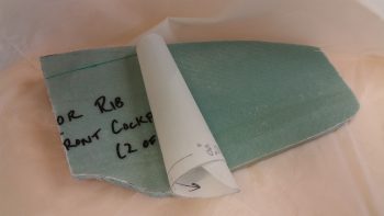
Then, through the requisite trial and error fitting and sanding repeat cycle, I finalized the shape and got it into place. My original location for this rib was very close to the stock location called for in the plans.
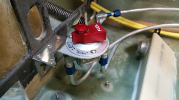
I then removed the fuel selector valve and its bracket to mount the fuel pump in place. I then remounted the fuel selector valve and bracket. I taped up the fuel selector valve because it’s a nice looking piece, and as I was mounting and removing it I noted that it was laying in a pile of tools, files, sanding blocks, etc. and for a minute thought that I had scratched it pretty good… I clearly needed to better protect the nice finish during the build process.
The fit of the left side of the fuel selector valve bracket and the inside of the left fuel pump frame is about as exact as could be. Too close actually and I’ll need to trim the left side of the fuel valve bracket by at least 0.050″ to allow for clearance. The clearance on both the instrument panel bulkhead attach bolts and the upper bracket attach screws is all good.
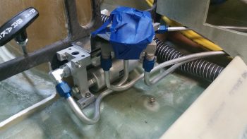
I then started the multi-hour process of shaping and terminating the 3/8″ aluminum tubing that makes up the fuel selector valve to fuel pump crossover line. Amazing how many distinct requirements I had on such a short cross-connect tube. First, I discovered I needed a distinct dogleg in the lower horizontal section of the tube to curve around the left tank feed line coming into the left side of the fuel valve. Then there was the curve back, at about a 45° angle, to intersect the fuel pump fitting, which is a distinct angle change in comparison to the other side attached to the fuel selector valve.
Piece of cake, right?! Yeah, after a couple of hours and definitely getting my tube cutting, bending and flaring practice in for the year! Obviously I finally got it, and it’s the last bit of fuel line tubing bending I have to do on this plane! (I still have the brake cross-connect lines to do…)
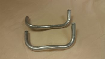
Here are the previous 2 failed attempts . . .
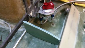
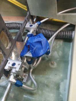
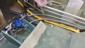
Another shot of the fuel selector valve to fuel pump crossover line, along with the other fuel valve connections. Note the heater air SCAT tubing I set in place on the pilot thigh support wedge duct outlet.
I then spent a good hour getting the thigh support ribs configured and set in place. As I stated previously, I had originally planned on having the left thigh support rib set in place at the plans location. I even started notching the foam out to allow for the fuel pump’s left side fitting and the cross-connect fuel line to the fuel valve. After pondering it for a bit I realized that it would just take too much work both in configuring, constructing and glassing the left rib simply to keep it in place at the plan’s location. By kicking it outboard an inch to the left I eliminated all these issues & headaches…. so, that’s the spot!
On the right side there is simply no way that the rib can connect all the way from the aft side thigh support wedge duct to the bottom of the instrument panel bulkhead. Not unless I never planned on removing the fuel pump.
Now, obviously hind sight is 20/20, but had I NOT used Clickbonds on the lower fuel pump mounting tabs and instead used embedded nutplates, I could have eliminated a LOT of my fuel pump mounting issues. First, I could take the right side rib all the way to the bottom of the instrument panel bulkhead since I would have been able to slide the fuel pump in vs drop it in straight down. Even more helpful would be the fact that I wouldn’t have to remove the fuel valve bracket to get the fuel pump in or out…. the saving grace being that I don’t foresee having to be installing and/or removing the fuel pump a lot once the airplane is flying.
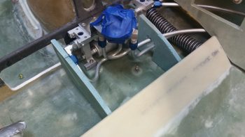
Here’s a wider angle shot showing all the fuel line runs in the pilot seat area, pretty much close to the original style as per plans, with some obvious distinct configuration tweaks I made on the fuel pump and fuel valve mounting locations.
I should note that the lonely Clickbond on the fuselage floor just aft of the fuel pump was originally for the 90 micron fuel filter supplied (and required) with the EFII fuel boost pump. I mounted this filter, and thus the Clickbond, prior to making my decision to go with the Holley Hydramat fuel pickups in the thigh support sump tanks. Since the Hydramats filter to 15 microns, and I have one final 32 micron filter [as required by the Silver Hawk fuel injection system] at the firewall, there is simply no need for this 90 micron filter. So…. out it went!
Between now and next week I do plan on continuing to knock out these build tasks, but admittedly it will start to slow the closer I get in heading down to Marco’s for our flying out to Rough River. Hopefully I’ll see a bunch of you there!
Love the way the handle turned out.
Thanks Bro!