
I started out today having a discussion with Mike from ElectroAir. I had a few questions on the installation of the ElectroAir electronic ignition system, most being just crosschecks on what I was planning on doing and that I wasn’t going to screw anything up doing it!
There are a couple of connectors on their EIS (not GRT) Controller harness that I inquired about: the first connector –that I want gone– are on the wires running to the coils, and the second just a connector inexplicably (to me) placed on the controller’s ground wire. The first will get replaced after I run the wires through the firewall to the coil, the latter connector will get removed altogether. Both with the blessing of ElectroAir.
All this really relates to wire runs both in the hellhole and through the firewall. That, in turn, relates to space required for wiring transiting holes through the firewall in the D-Deck / Turtle Deck / GIB headrest.
I then had a quick chat with B&C about the mounting requirements for the SD-8 Backup Alternator’s voltage regulator. The new electrical system requirement I picked up from them is that it’s highly recommended that I have a cooling fan for the SD-8 voltage regulator since apparently it runs a little on the warm side.
So, fan on the list to integrate into the GIB headrest.
I then integrated this new fan requirement into the electrical system, as well as moved the ElectroAir MAP sensor from the engine compartment into the Hell Hole, by reworking a number of my electrical diagrams.
Since I was on the computer upstairs updating my electrical diagrams, I took a good half hour to familiarize myself with Mike Beasley’s engine baffle templates. I cut a few of the template pages into pieces so I could better get them organized, and after I had a decent understanding of what was going on I left them alone & headed down to the shop.
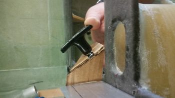
In the shop, I started off by determining the angle for the riser mount I’ll build to house the parking brake T-handle on the left side of the nose gear viewing window, and then a mirror one on the right for the nose hatch release T-handle.
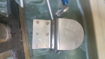
After spending a good hour determining dimensions & drafting up some ideas on mounting these T-handles, I then got to work on cutting, forming, constructing, and mounting the top fuel selector valve bracket to the lower fuel valve bracket.
Although I plan on having some sort of support brace to assist in securing the fuel selector valve, I also had planned on the valve being mounted a little aft and a bit higher than the plans valve. Thus, the mounting of my fuel valve would incorporate a significant stepped cantilever design for the upper valve bracket.
Allowing for this stepped cantilever design, I chose a 0.090″ thick piece of scrap 6061 for my stepped upper bracket. I don’t have a bending brake, so I resorted to clamps (one of which I broke!), 2x4s, and a couple of different hammers to bend this piece of metal to my will . . . ha! Moreover, (specifically for Marco) I started off by cutting the scrap 6061plate to its 3″ width using my Skil saw that was conveniently available. For the curved aft end of the bracket I used my jig saw with a metal blade installed.
I then clamped & pounded, clamped & pounded <insert choice curse words here!>, replaced a broken clamp, and then clamped & pound some more. I had my phone charging so I didn’t get any pics of this sequence, but suffice it to say it worked out well enough. Again, it won’t win any beauty contests, but it’s strong as can be and it’s pretty darn straight to boot!
I then used my new Cleco clamp to help hold the bracket in place (in hindsight I won’t use a Cleco clamp on something with a nice finish –which ironically is why I chose this clamp– since it marred the finish. Since this plate will get covered or painted anyway, it’s a good lesson learned) and drilled pilot holes in the aft row of screw mounting holes, placing a Cleco in each hole as I drilled them.
Due to the width of the drill, I couldn’t drill the forward screw mounting holes without imparting an angle on each of the holes.
So I removed the Clecoed-together upper and lower bracket assembly and widened the screw mounting holes to 1/8″, with the subsequent Clecos getting mounted into each hole as it was drilled.
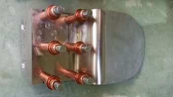
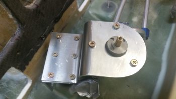
Due to my haste I also failed to get a shot of the 6 x K1000-8 nutplate assemblies that I drilled and riveted into place. I had considered simply using 4 x #10 screws to secure the upper & lower plates together, but then after some thought I went with 6 smaller #8 screws. Again, in hindsight I could have gone either way and now think the 6 screws may be a slight overkill, but it’s definitely secure! Clearly, I needed 2 standard and 4 corner nutplates for this job.
Once the nutplates were installed, I then mounted the top fuel valve bracket to the lower. I’ll also state that the alignment deamons reared their ugly head here –despite my intense efforts otherwise– and somehow my bracket alignment got off kilter about 0.030-0.040″. To be certain, the left & right edges weren’t perfectly aligned when I started, but the front edge was. So I ended up filing the front edge to make the edge straight and allow for it to fit flush against the lower instrument panel.
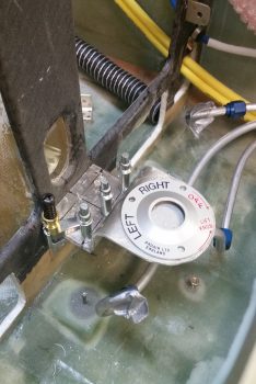
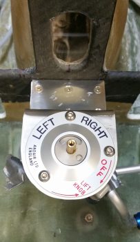
I then rounded up my installation instructions for the Andair fuel selector valve. Now, the Andair install directions would have you install the valve with the Left tank straight 90° left, the Right tank straight up, and the OFF position 90° to the right, like this: ⊥ (L-9 O’clock, R-12 O’clock, OFF-3 O’clock). . . I changed that by rotating the valve a bit clockwise so the my Left & Right tank valve handle positions would be symmetrical, with my Left tank at the 10 O’clock position (45° left), my Right tank at the 2 O’clock position (45° right) in a ∨ fashion, and my OFF at the 5 O’clock position (45° low right).
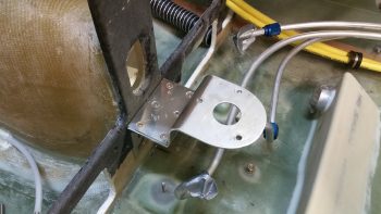
I then drilled the 1″ round center Andair fuel valve mounting hole, drilled the 3 each #10 screw mounting holes, and mounted the fuel selector valve.
I then removed the valve, countersunk the 6 x #8 bracket screws, and remounted the fuel valve bracket assembly onto the lower instrument panel bulkhead.
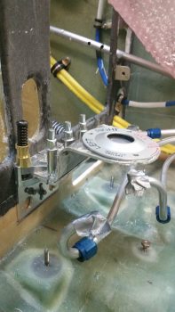
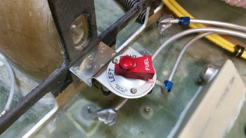
I then remounted the Andair fuel selector valve with its cover plate.
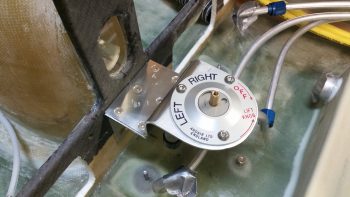
I then mounted the fuel valve handle.
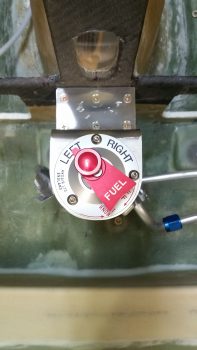
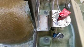
And the parting shot of the evening: the fuel selector valve officially installed!
Tomorrow I’ll continue my pilot’s seat area build tasks. To be clear, I can’t do the final install on the GIB area air & heat ducts until I figure out the cable runs and lengths to the 3 valves installed in the ducts. To do this, I need to know the mounting configuration of the valve handles in the left pilot armrest. Thus, in order to get the left armrest installed, I need to get the pilot seat thigh support ribs and cover in place. So in an odd twist, the fuel valve I finished installing tonight has a direct bearing on me getting the GIB ducts installed!