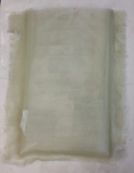
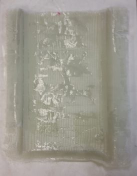
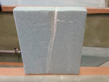
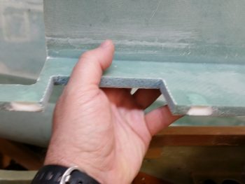
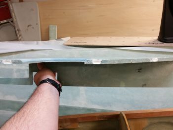
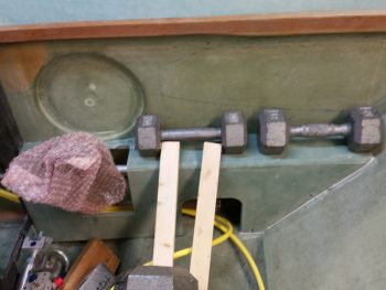
I started off today pulling the “map” & document case off the wall. Thankfully, it came off without too much of a fight. I quickly pried away the entombed maps, freed them and threw away the ton of tape from this endeavor.
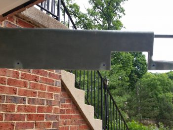
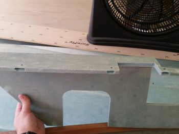
I then inspected it to see how it came out. It looks pretty good, with some obvious cleaning up required, especially on the inside.
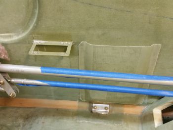
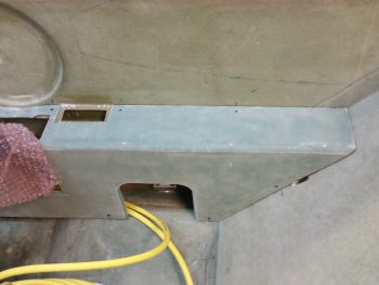
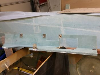
I then pulled the peel ply and trimmed up the “map” & document case and using a couple of pieces of duct tape did a quick mockup on the fuselage sidewall.
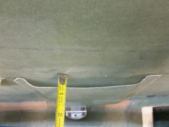
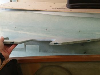
I also checked its depth. In the pic below it’s sitting at about 0.45″ from side wall to “map” case wall. But remember, there’s tape under the tabs, and I’ll be able to control at least the top depth by the cutout in the right armrest. The end result is that it should be around 0.4″± ~0.2″.
With the “map” & document case looking ok, I moved on to the right arm rest. With the “map” case on the side wall I was able to determine where my top armrest screw attach points would be located. I then determined the rest of the attach points for the right arm rest, except the very top front and very bottom front areas. These will need special attention based on what kind of stuff traverses these spots.
With my armrest screw attach points known, I used a mounting tab to mark up where the screw hole would be (a very close approximation did fine here). I then dug the foam out so that when I filled in the resulting divot with 30/70 flocro, I would have a nice hardpoint for each screw to mount into.
Finished with my armrest screw hard points, I vacuumed them out & filled them with flocro using fast hardener (results shown later below).
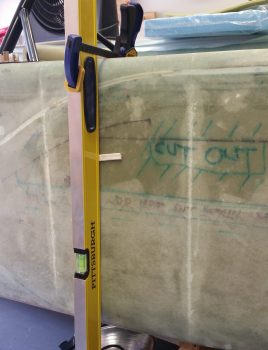
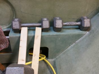
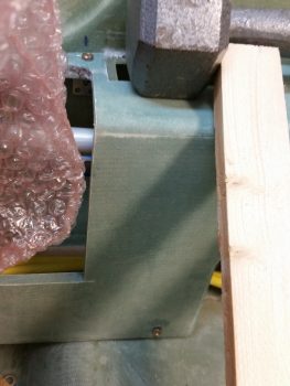
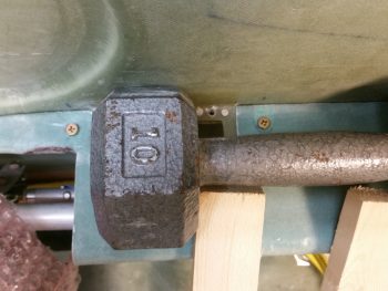
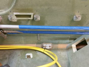
I then set my sights on the GIB thigh support sump tanks. My first quest was to ensure that I didn’t damage my embedded brake lines that traverse the bottom of the fuselage, one on each side. I placed a level along the outside of the fuselage and determined the distance that the brake line was away from the sidewall. I then marked the inside with an extrapolated, but close, measurement for the brake lines on each side… both using this method.
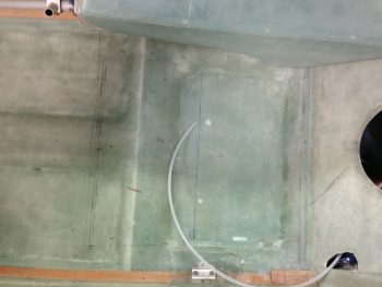
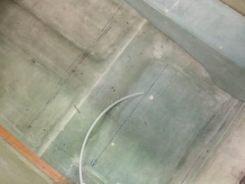
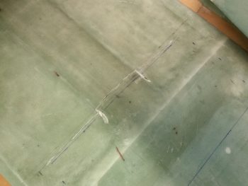
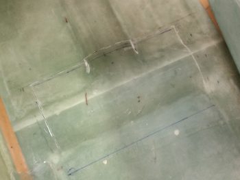
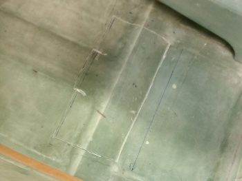
With knowledge of my brake line locations in hand, I could then more accurately draw out my thigh support sump design on the floor of the back seat.
Just as a point of historical note: these pics below are the last two pics showing the area on the seat pan that I was most proud of . . . and then destroyed! Such is the way of composite homebuilts eh?
Another quick side note: To implement my sump design I needed some 1″ Divinycell for a mini-bulkhead in the right front corner of the sump assembly. Well, I didn’t have 1″ pieces large enough so I micro’d these two pieces together to make this bulkhead piece, which I plan to use in the next few days.
I then put on my mask, drew a big breath, fired up my Fein saw and started cutting! Here’s the front border line of the sump(s) that I started cutting first.
I then cut the interim sides of the sump area. I moved the cutting lines in about 0.5″ to ensure I didn’t cut into the brake lines. I’ll then slowly moved my way out to ensure not to damage the brake lines.
I then cut the back line to complete the major glass cutting of this operation.
Then, using a utility knife, I slowly pried off the top glass of my GIB seat glass.
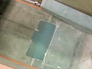 I started removing the foam by hand, but that lasted for about 5 minutes. This stuff is tough! I then employed the services of the Fein saw once again and went to town on the foam.
I then employed another power tool: an orbital sander and sanded down all the remaining high tops of the foam. It did a great job as you can see, but man did it produce some nasty dust…. and a lot of it too.
In the pic below you can see on the right side (top of pic) where I’ve started to remove the foam slowly under the fiberglass, about a half inch in. This is to ensure –again– that if I hit the brake line, it’s only by hand with a razor knife moving somewhat slowly. I did not however, encounter the brake lines which should be about where the top/right set of dashed lines are.
Having removed the foam from each side, I then carefully used the Fein saw again the trim away the half inch edge of glass. I then resanded the edges and in the forward outboard corners as well, which I obviously couldn’t get with the orbital sander.
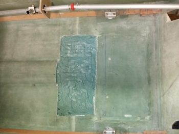
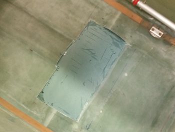
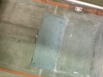
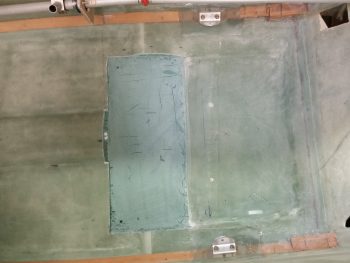
Here’s a final shot of the freshly contoured GIB seat area ready to be glassed in prep for the thigh support sump build. You can also see in the pics below & above the marked locations for the sump drains.
After I took this shot, I met a buddy of mine for dinner.
Upon returning home, I checked out the flocro in the right armrest. Here’s a couple of shots (albeit crappy!).
I then drilled holes into the armrest and riveted up 5 tabs with nutplates. To limit my variables when installing the armrest, tonight I only floxed in 4 of these 5 mounting tabs (the one at the far right –which is the front side mounting tab– didn’t get floxed tonight).
Not only did I flox 4 of the mounting tabs in place, obviously attached to the right armrest, but I also filled the gap between the armrest and pilot seat bulkhead with micro. This was planned and I had already placed a long piece of clear plastic tape on the seat in position.
Just a slightly closer shot.
Here’s a shot of two of the armrest mounting tab screws.
And here’s the same one on the left, and another one just to the right of the intercom bracket.
At about 1.5 hours into mounting the right armrest with flox I started prepping 4 x 1-ply BID prepreg setups. I was checking the flox in the cup and after almost 2 hours had passed I unscrewed the armrest and pulled it free. With all that micro on the aft side that in itself was a bit of a chore.
Then I whipped up some flocro since I wanted some strength but not a lot of added weight. With the flox still just slightly tacky (green state) I cut off the flox fingers and covered the tabs with flocro, then laid up a ply of BID over each tab. I was planning on peel plying these layups, but it’s really late and I’d rather just hit the edges with some sandpaper later on.
I probably won’t layup any glass on the other right armrest mounting tabs and will let the flox just stand for itself. I did want to get about half of these with a ply of glass on them just for securing the armrest’s sake.
Tomorrow will be a light build day, but over the next few days I do plan on finishing up the thigh support sump assembly as well as the pilot seat area components. Again, this is all part of the push to be able to have a good assessment, knowledge and fitting of all the nose components. Once those are in place, I’ll work on finalizing the nose and concurrently knocking out those pesky wheel pants (nope, I haven’t forgot about those!).
