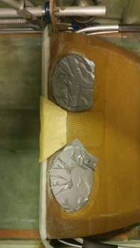
Today I started out by cutting a small wedge of Kevlar to place over and around the sump’s front corner edge Nylaflow conduit. I wanted to make sure that when the GIB steps into & out of the back seat that the Nylaflow conduit doesn’t get damaged.
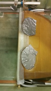
I then cut the 2nd ply of BID to get laid up over the first ply of sump LE BID and the new piece of Kevlar. I then wetted out the BID in place on the sump & then peel plied it after the layup was complete.
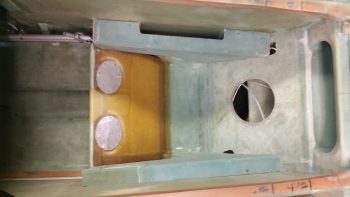
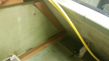
I had to make a Harbor Freight run, so after a number of hours I pulled the peel ply and cleaned up the sump front edge Nylaflow covering layup. This is what the GIB back seat area is looking like these days. With that last layup I’m done with fiber-glassing on the thigh support fuel sump, unless something new pops up of course.
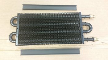
I then set my sights on the oil heating system. After inspecting the heat exchanger, I realized I could simply pop off the plastic protective runners on each side. It didn’t take long looking at the heat exchanger to realize that my airflow in, through and out the heat exchanger was going to take place via the long sides of the unit.
I then cut some 2″ wide cardboard strips out to represent the width, albeit not the depth (which is 0.75″) of the heating & fresh air ducts. I played around with this whole setup for a good 45 minutes before determining what my next steps will be. Since there’s no exact plans for building the ductwork for the heating and fresh air system, this will be a bit more slow in the creation and build of this whole thing. Plus, I got some good data points today and will continue to press on with building the oil heat system over the next 2-3 weeks.
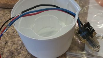
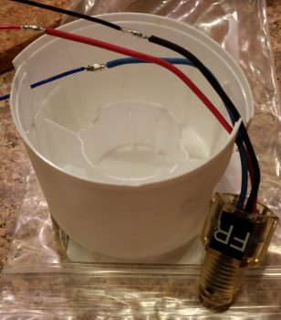
I was also finally able to get the sump low fuel level sensor wires soldered tonight. Since these are very low current sensors I’m using 24 AWG wiring for the leads that will traverse through the front sump wall Nylaflow conduits up to the Triparagon, where they’ll connect to power, ground and EFIS data input.
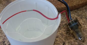
Here is the initial splice of the red wire of the left sensor.
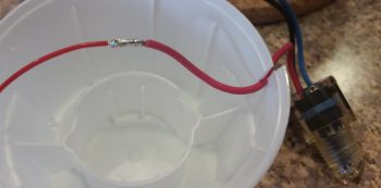
And immediately after I soldered the wires together.
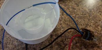
Here’s the blue wire soldered . . .
And all the sensor wires cut shorter and solder-spliced in this pic.
I also did the same process for the right sump tank’s low fuel level sensor. Tomorrow I’ll heat shrink all the splices to finish up this task.
I also trimmed the edges of the sump low fuel level sensor protective covers as well, but failed to get a pic of them after they were trimmed up. Tomorrow I’ll add a pic of the trimmed covers. I’ll also continue working getting the sump low fuel level sensors installed and under the protective covers while concurrently working the oil heating and fresh air intake system.

